


Rev. 1.00, 05/04, page 309 of 544
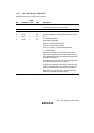
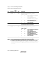
13.4.2 Initialization
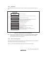
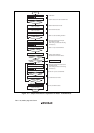
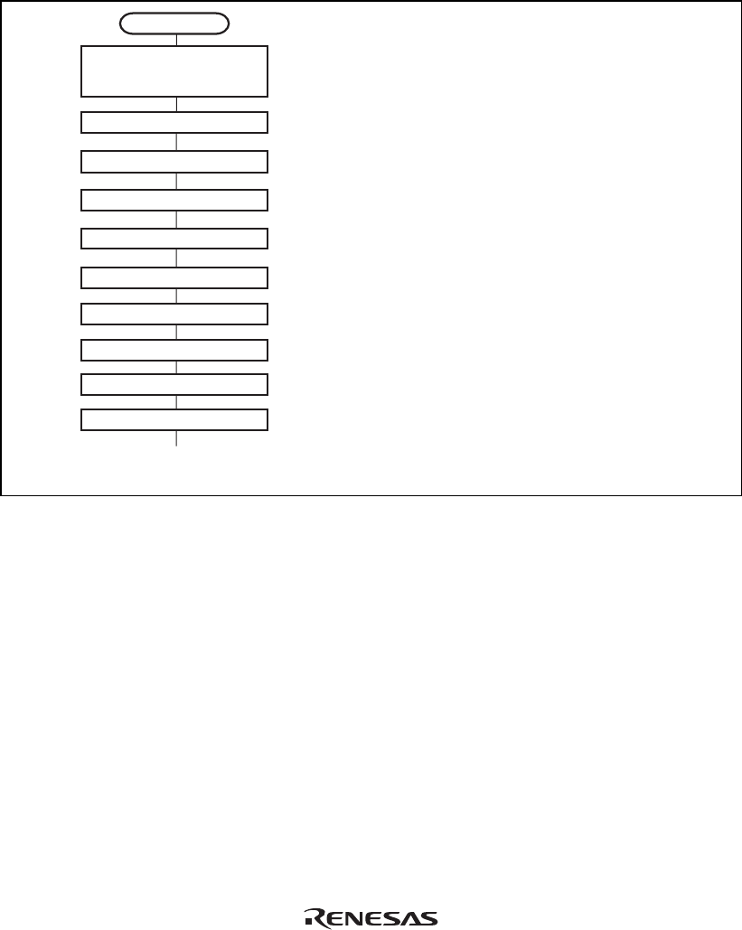
Initialize the IIC by the procedure shown in figure 13.6 before starting transmission/reception of
data.
Start initialization
Set MSTP4 = 0 (IIC_0)
MSTP3 = 0 (IIC_1)
(MSTPCRL)
Set ICE = 0 in ICCR
Set ICSR
Set STCR
Cancel module stop mode
Set the first and second slave addresses and IIC communication format
(SVA6 to SVA0, FS, SVAX6 to SVAX0, and FSX)
Enable ICMR and ICDR to be accessed
Use SCL/SDA pin as an IIC port
Set transfer rate (IICX)
Enable the CPU accessing to the IIC control register and data register
Set communication format, wait insertion, and transfer rate
(MLS, WAIT, CKS2 to CKS0)
Enable interrupt
(STOPIM, HNDS, ALIE, ALSL, FNC1, and FNC0)
Set acknowledge bit (ACKB)
Set ICMR
Set ICCR
Set IICE = 1 in STCR
Set SAR and SARX
Set ICE = 1 in ICCR
Set ICXR
<< Start transmit/receive operation >>
Set interrupt enable, transfer mode, and acknowledge decision
(IEIC, MST, TRS, and ACKE)
Enable SAR and SARX to be accessed
Figure 13.6 Sample Flowchart for IIC Initialization
Note: Be sure to modify ICMR after transmit/receive operation has been completed. If ICMR is
modified during transmit/receive operation, bit counter BC2 to BC0 will be modified
erroneously, thus causing incorrect operation.
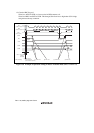
13.4.3 Master Transmit Operation
In I
2
C bus format master transmit mode, the master device outputs the transmit clock and transmit
data, and the slave device returns an acknowledge signal.
Figure 13.7 shows the sample flowchart for the operations in master transmit mode.