


Rev. 1.00, 05/04, page 472 of 544
When the RES pin is driven low, system clock oscillation is started. At the same time as system
clock oscillation starts, the system clock is supplied to the entire LSI. Note that the RES pin must
be held low until clock oscillation stabilizes. When the RES pin goes high after clock oscillation
stabilizes, the CPU begins reset exception handling.
When the STBY pin is driven low, software standby mode is cancelled and a transition is made to
hardware standby mode.
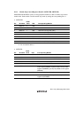
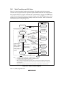
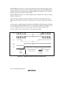
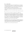
Figure 20.3 shows an example in which a transition is made to software standby mode at the
falling edge of the NMI pin, and software standby mode is cleared at the rising edge of the NMI
pin.
In this example, an NMI interrupt is accepted with the NMIEG bit in SYSCR cleared to 0 (falling
edge specification), then the NMIEG bit is set to 1 (rising edge specification), the SSBY bit is set
to 1, and a SLEEP instruction is executed, causing a transition to software standby mode.
Software standby mode is then cleared at the rising edge of the NMI pin.
Oscillator
φ
NMI
NMIEG
SSBY
NMI exception
handling
NMIEG = 1
SSBY = 1
SLEEP instruction
Software standby mode
(power-down mode)
Oscillation
stabilization
time t
OSC2
NMI exception
handling
Figure 20.3 Application Example in Software Standby Mode