


TIMH265B_000020040200 Rev. 1.00, 05/04, page 183 of 544
Section 10 8-Bit Timer (TMR)
This LSI has an on-chip 8-bit timer module (TMR_0, TMR_1, TMR_Y, TMR_X, TMR_B, and
TMR_A) with six channels operating on the basis of an 8-bit counter. The 8-bit timer module can
be used as a multifunction timer in a variety of applications, such as generation of counter reset,
interrupt requests, and pulse output with an arbitrary duty cycle using a compare-match signal
with two registers.
10.1 Features
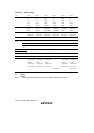
Select of clock sources
The counter input clock can be six internal clocks*
1
and an external clock
Select of three ways to clear the counters
The counters can be cleared on compare-match A or compare-match B, or by an external reset
signal
Timer output controlled by two compare-match signals
The timer output signal in each channel is controlled by two independent compare-match
signals, enabling the timer to be used for various applications, such as the generation of
pulse output or PWM output with an arbitrary duty cycle
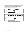
Cascading of two channels
Cascading of TMR_0 and TMR_1,TMR_Y and TMR_X*
2
or TMR_B and TMR_A
Operation as a 16-bit timer can be performed using TMR_0/TMR_Y/TMR_B as the upper
half and TMR_1/TMR_X/TMR_A as the lower half (16-bit count mode)
TMR_1/TMR_X/TMR_A can be used to count TMR_0/TMR_Y/TMR_B compare-match
occurrences (compare-match count mode)
Multiple interrupt sources for each cannels
Compare-match A: TMR_0, TMR_1, TMR_Y, TMR_B and TMR_A
Compare-match B: TMR_0, TMR_1, TMR_Y, TMR_B and TMR_A
Overflow: TMR_0, TMR_1, TMR_Y, TMR_B and TMR_A
Input capture: TMR_X and TMR_A
Input capture function (TMR_X and TMR_A)
Notes: 1. The program development tool (emulator) supports three internal clocks.
2. The program development tool (emulator) does not support this function.