


Rev. 1.00, 05/04, page 377 of 544
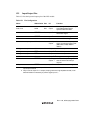
15.3.2 Host Interface Control Registers 2 and 3 (HICR2, HICR3)
Bits 6 to 0 in HICR2 control interrupts from the host interface (LPC) module to the slave
processor (this LSI). Bit 7 in HICR2 and HICR3 monitor host interface pin states.
The pin states can be monitored regardless of the host interface operating state or the operating
state of the functions that use pin multiplexing.
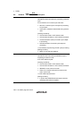
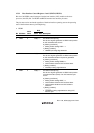
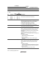
• HICR2
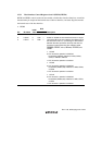
R/W
Bit Bit Name
Initial
Value
Slave Host Description
7 GA20 Undefined R — GA20 Pin Monitor
6 LRST 0 R/(W)* — LPC Reset Interrupt Flag
This bit is a flag that generates an ERRI interrupt when
an LPC hardware reset occurs.
0: [Clearing conditions]
• Writing 0 after reading LRST = 1
1: [Setting condition]
• LRESET pin falling edge detection
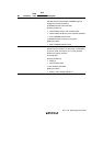
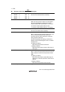
5 SDWN 0 R/(W)* — LPC Shutdown Interrupt Flag
This bit is a flag that generates an ERRI interrupt when
an LPC hardware shutdown request is generated.
0: [Clearing conditions]
• Writing 0 after reading SDWN = 1
• LPC hardware reset and LPC software reset
1: [Setting condition]
• LPCPD pin falling edge detection
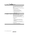
4 ABRT 0 R/(W)* — LPC Abort Interrupt Flag
This bit is a flag that generates an ERRI interrupt when
a forced termination (abort) of an LPC transfer cycle
occurs.
0: [Clearing conditions]
• Writing 0 after reading ABRT = 1
• LPC hardware reset and LPC software reset
• LPC hardware shutdown and LPC software
shutdown
1: [Setting condition]
• LFRAME pin falling edge detection during LPC
transfer cycle