


Rev. 1.00, 05/04, page 106 of 544
7.3.4 Pin Functions
• P37/SERIRQ, P36/LCLK, P35/LRESET, P34/LFRAME, P33/LAD3, P32/LAD2, P31/LAD1,
P30/LAD0
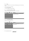
The pin function is switched as shown below according to the combination of the LPC3E to
LPC1E bits in HICR0 of the host interface (LPC) and the P3nDDR bit.
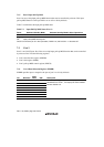
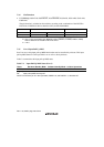
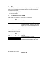
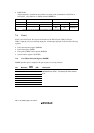
LPCmE All 0 Not all 0
P3nDDR 0 1 0
Pin Function P37 to P30 input pins P37 to P30 output pins LPC input/output pins
Note: The combination of bits not described in the above table must not be used.
m = 3 to 1: LPC input/output pins (SERIRQ, LCLK, LRESET, LFRAME, LAD3 to LAD0)
when at least one of LPC3E to LPC1E is set to 1.
n = 7 to 0
7.3.5 Port 3 Input Pull-Up MOS
Port 3 has an on-chip input pull-up MOS function that can be controlled by software. This input
pull-up MOS function can be specified as on or off on a bit-by-bit basis.
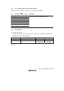
Table 7.4 summarizes the input pull-up MOS states.
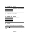
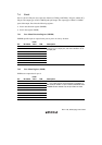
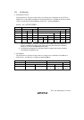
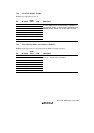
Table 7.4 Input Pull-Up MOS States (Port 3)
Reset Hardware Standby Mode Software Standby Mode In Other Operations
Off Off On/Off On/Off
[Legend]
Off: Input pull-up MOS is always off.
On/Off: On when the pin is in the input state, P3DDR = 0, and P3PCR = 1; otherwise off.