


Rev. 1.00, 05/04, page 416 of 544
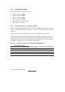
16.3 Register Descriptions
The A/D converter has the following registers.
• A/D data register A (ADDRA)
• A/D data register B (ADDRB)
• A/D data register C (ADDRC)
• A/D data register D (ADDRD)
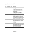
• A/D control/status register (ADCSR)
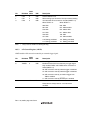
• A/D control register (ADCR)
16.3.1 A/D Data Registers A to D (ADDRA to ADDRD)
There are four 16-bit read-only ADDR registers, ADDRA to ADDRD, used to store the results of
A/D conversion. The ADDR registers, which store a conversion result for each channel, are shown
in table 16.2.
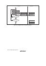
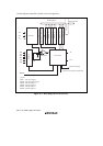
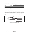
The converted 10-bit data is stored to bits 15 to 6. The lower 6-bit data is always read as 0.
The data bus between the CPU and the A/D converter is 8-bit width. The upper byte can be read
directly from the CPU, but the lower byte should be read via a temporary register. The temporary
register contents are transferred from the ADDR when the upper byte data is read. When reading
the ADDR, read the upper byte before lower byte or in word units.
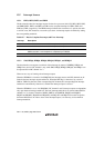
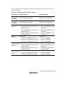
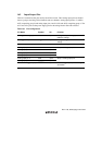
Table 16.2 Analog Input Channels and Corresponding ADDR Registers
Analog Input Channel
Group 0 Group 1 A/D Data Register to Store A/D Conversion Results
AN0 AN4 ADDRA
An1 AN5 ADDRB
AN2 ADDRC
AN3 ADDRD