


Rev. 1.00, 05/04, page 355 of 544
14.4 Operation
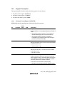
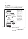
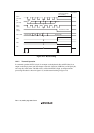
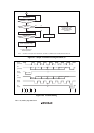
14.4.1 Receive Operation
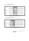
In a receive operation, both KCLK (clock) and KD (data) are outputs on the keyboard side and
inputs on this LSI chip (system) side. KD receives a start bit, 8 data bits (LSB-first), an odd parity
bit, and a stop bit, in that order. The KD value is valid when KCLK is low. A sample receive
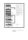
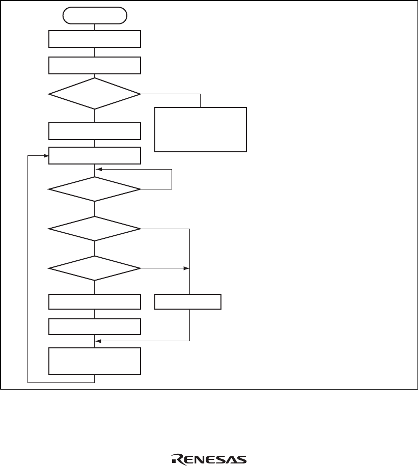
processing flowchart is shown in figure 14.3, and the receive timing in figure 14.4.
Start
Set KBIOE bit
Read KBCRH
KCLKI
and KDI bits both 1?
Set KBE bit
Receive enabled state
KBF = 1?
PER = 0?
KBS = 1?
Read KBBR
Receive data processing
Clear KBF flag
(receive enabled state)
Keyboard side in data
transmission state.
Execute receive abort
processing.
Error handling
[1] Set the KBIOE bit to 1 in KBCRL.
[2] Read KBCRH, and if the KCLKI
and KDI bits are both 1, set the
KBE bit (receive enabled state).
[3] Detect the start bit output on the
keyboard side and receive data in
synchronization with the fall of
KCLK.
[4] When a stop bit is received, the
keyboard buffer controller drives
KCLK low to disable keyboard
transmission (automatic I/O inhibit).
If the KBIE bit is set to 1 in KBCRH,
an interrupt request is sent to the
CPU at the same time.
[5] Perform receive data processing.
[6] Clear the KBF flag to 0 in KBCRL.
At the same time, the system
automatically drives KCLK high,
setting the receive enabled state.
The receive operation can be
continued by repeating steps [3] to [6].
[1]
[2]
[3]
[4]
[5]
[6]
Yes
No
Yes
Yes
Yes
No
No
No
Figure 14.3 Sample Receive Processing Flowchart