


Rev. 1.00, 05/04, page 249 of 544
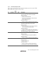
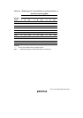
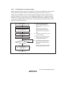
12.3.10 Serial Pin Select Register (SPSR)
SPSR selects the serial I/O pins. SPSR should be set before initialization. Do not set during
communication.
Bit
Bit
Name
Initial
Value R/W Description
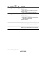
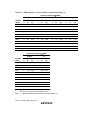
7 SPS1 0 R/W Serial Port Select
Selects the serial I/O pins.
0: P86/SCK1, P85/RxD1, P84/TxD1
1: P52/ExSCK1, P51/ExRxD1, P50/ExTxD1
6 to 0 — All 0 R/W Reserved
The initial value should not be changed.
Note: The program development tool (emulator) does not support SPSR.
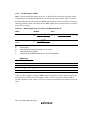
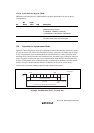
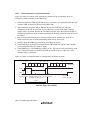
12.4 Operation in Asynchronous Mode
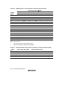
Figure 12.2 shows the general format for asynchronous serial communication. One frame consists
of a start bit (low level), followed by transmit/receive data, a parity bit, and finally stop bits (high
level). In asynchronous serial communication, the transmission line is usually held in the mark
state (high level). The SCI monitors the transmission line, and when it goes to the space state (low
level), recognizes a start bit and starts serial communication. Inside the SCI, the transmitter and
receiver are independent units, enabling full-duplex communication. Both the transmitter and the
receiver also have a double-buffered structure, so that data can be read or written during
transmission or reception, enabling continuous data transfer and reception.
LSB
Start
bit
MSB
Idle state
(mark state)
Stop bit
0
Transmit/receive data
D0 D1 D2 D3 D4 D5 D6 D7 0/1 1 1
1
1
Serial
data
Parity
bit
1 bit 1 or 2 bits7 or 8 bits 1 bit or
none
One unit of transfer data (character or frame)
Figure 12.2 Data Format in Asynchronous Communication
(Example with 8-Bit Data, Parity, Two Stop Bits)