


Rev. 1.00, 05/04, page 83 of 544
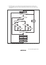
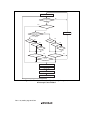
Figure 5.6 shows a flowchart of the interrupt acceptance operation.
1. If an interrupt source occurs when the corresponding interrupt enable bit is set to 1, an
interrupt request is sent to the interrupt controller.
2. According to the interrupt control level specified in ICR, the interrupt controller only accepts
an interrupt request with interrupt control level 1 (priority), and holds pending an interrupt
request with interrupt control level 0 (no priority). If several interrupt requests are issued, an
interrupt request with the highest priority is accepted according to the priority order, an
interrupt handling is requested to the CPU, and other interrupt requests are held pending.
3. An interrupt request with interrupt control level 1 is accepted when the I bit is cleared to 0, or
when the I bit is set to 1 while the UI bit is cleared to 0.
An interrupt request with interrupt control level 0 is accepted when the I bit is cleared to 0.
When the I bit is set to 1, only an NMI or address break interrupt request is accepted, and other
interrupts are held pending.
When both the I and UI bits are set to 1, only an NMI or address break interrupt request is
accepted, and other interrupts are held pending.
When the I bit is cleared to 0, the UI bit is not affected.
4. When the CPU accepts an interrupt request, it starts interrupt exception handling after
execution of the current instruction has been completed.
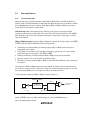
5. The PC and CCR are saved to the stack area by interrupt exception handling. The PC saved on
the stack shows the address of the first instruction to be executed after returning from the
interrupt handling routine.
6. The I and UI bits in CCR are set to 1. This masks all interrupts except for an NMI or address
break interrupt.
7. The CPU generates a vector address for the accepted interrupt and starts execution of the
interrupt handling routine at the address indicated by the contents of the vector address in the
vector table.