


Rev. 1.00, 05/04, page 439 of 544
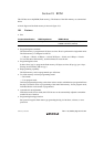
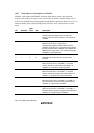
18.5.2 Flash Memory Control Register 2 (FLMCR2)
FLMCR2 monitors the state of flash memory programming/erasing protection (error protection)
and sets up the flash memory to transit to programming/erasing mode. FLMCR2 is initialized to
H'00 by a reset or in hardware standby mode. The ESU and PSU bits are cleared to 0 in software
standby mode, sub-active mode, sub-sleep mode, or watch mode, or when the SWE bit in
FLMCR1 is cleared to 0.
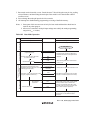
Bit Bit Name
Initial
Value R/W Description
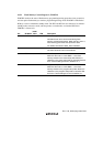
7 FLER 0 R Flash memory error
Indicates that an error has occurred during flash
memory programming/erasing. When this bit is set to 1,
flash memory goes to the error-protection state.
For details, see section 18.9.3, Error Protection.
6 to 2 — All 0 R/(W) Reserved
The initial values should not be modified.
1 ESU 0 R/W Erase Setup
When this bit is set to 1 while SWE = 1, the flash
memory transits to the erase setup state. When it is
cleared to 0, the erase setup state is cancelled. Set this
bit to 1 before setting the E bit in FLMCR1 to 1.
0 PSU 0 R/W Program Setup
When this bit is set to 1 while SWE = 1, the flash
memory transits to the program setup state. When it is
cleared to 0, the program setup state is cancelled. Set
this bit to 1 before setting the P bit in FLMCR1 to 1.