


Rev. 1.00, 05/04, page 203 of 544
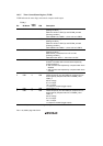
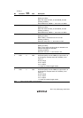
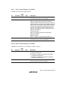
10.3.9 Timer Connection Register I (TCONRI)
TCONRI controls the input capture function.
Bit Bit Name
Initial
Value R/W Description
7 to 5 — All 0 R/W Reserved
The initial value should not be changed.
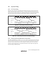
4 ICST 0 R/W Input Capture Start Bit
TMR_X has input capture registers (TICRR and
TICRF). TICRR and TICRF can measure the width of a
pulse by means of a single capture operation under the
control of the ICST bit. When a rising edge followed by
a falling edge is detected on TMRIX after the ICST bit
is set to 1, the contents of TCNT at those points are
captured into TICRR and TICRF, respectively, and the
ICST bit is cleared to 0.
[Clearing condition]
When a rising edge followed by a falling edge is
detected on TMRIX
[Setting condition]
When 1 is written in ICST after reading ICST = 0
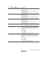
3 to 0
— All 0 R/W Reserved
The initial values should not be modified.
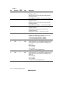
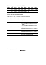
10.3.10 Timer Connection Register S (TCONRS)
TCONRS selects whether to access TMR_X or TMR_Y registers.
Bit Bit Name
Initial
Value R/W Description
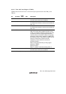
7 TMR_X/Y 0 R/W TMR_X/TMR_Y Access Select
For details, see table 10.4.
0: The TMR_X registers are accessed at addresses
H'(FF)FFF0 to H'(FF)FFF5
1: The TMR_Y registers are accessed at addresses
H'(FF)FFF0 to H'(FF)FFF5
6 to 0 All 0 R/W Reserved
The initial values should not be modified.