


Rev. 1.00, 05/04, page 371 of 544
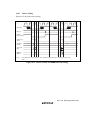
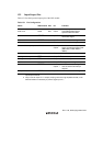
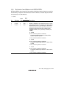
15.3.1 Host Interface Control Registers 0 and 1 (HICR0, HICR1)
HICR0 and HICR1 contain control bits that enable or disable host interface functions, control bits
that determine pin output and the internal state of the host interface, and status flags that monitor
the internal state of the host interface.
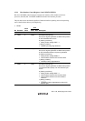
• HICR0
R/W
Bit Bit Name
Initial
Value
Slave Host Description
7
6
5
LPC3E
LPC2E
LPC1E
0
0
0
R/W
R/W
R/W
—
—
—
LPC Enable 3 to 1
Enable or disable the host interface function in single-
chip mode. When the host interface is enabled (one of
the three bits is set to 1), processing for data transfer
between the slave processor (this LSI) and the host
processor is performed using pins LAD3 to LAD0,
LFRAME, LRESET, LCLK, SERIRQ, CLKRUN, and
LPCPD.
• LPC3E
0: LPC channel 3 operation is disabled
No address (LADR3) matches for IDR3, ODR3,
STR3, or TWR0 to TWR15
1: LPC channel 3 operation is enabled
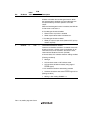
• LPC2E
0: LPC channel 2 operation is disabled
No address (H'0062, 66) matches for IDR2, ODR2,
or STR2
1: LPC channel 2 operation is enabled
• LPC1E
0: LPC channel 1 operation is disabled
No address (H'0060, 64) matches for IDR1, ODR1,
or STR1
1: LPC channel 1 operation is enabled