


Rev. 1.00, 05/04, page 399 of 544
Regular A20 Gate Operation: Output of the A20 gate signal can be controlled by an H'D1
command followed by data. When the slave processor (this LSI) receives data, it normally uses an
interrupt routine activated by the IBF1 interrupt to read IDR1. At this time, firmware copies bit 1
of data following an H'D1 command and outputs it at the gate A20 pin.
Fast A20 Gate Operation: The internal state of GA20 output is initialized to 1 when FGA20E =
0. When the FGA20E bit is set to 1, P81/GA20 is used for output of a fast A20 gate signal. The
state of the P81/GA20 pin can be monitored by reading the GA20 bit in HICR2.
The initial output from this pin will be a logic 1, which is the initial value. Afterward, the host
processor can manipulate the output from this pin by sending commands and data. This function
is only available via the IDR1 register. The host interface decodes commands input from the host.
When an H'D1 host command is detected, bit 1 of the data following the host command is output
from the GA20 output pin. This operation does not depend on firmware or interrupts, and is faster
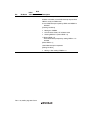
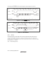
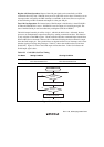
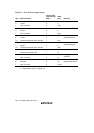
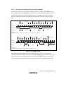
than the regular processing using interrupts. Table 15.3 shows the conditions that set and clear
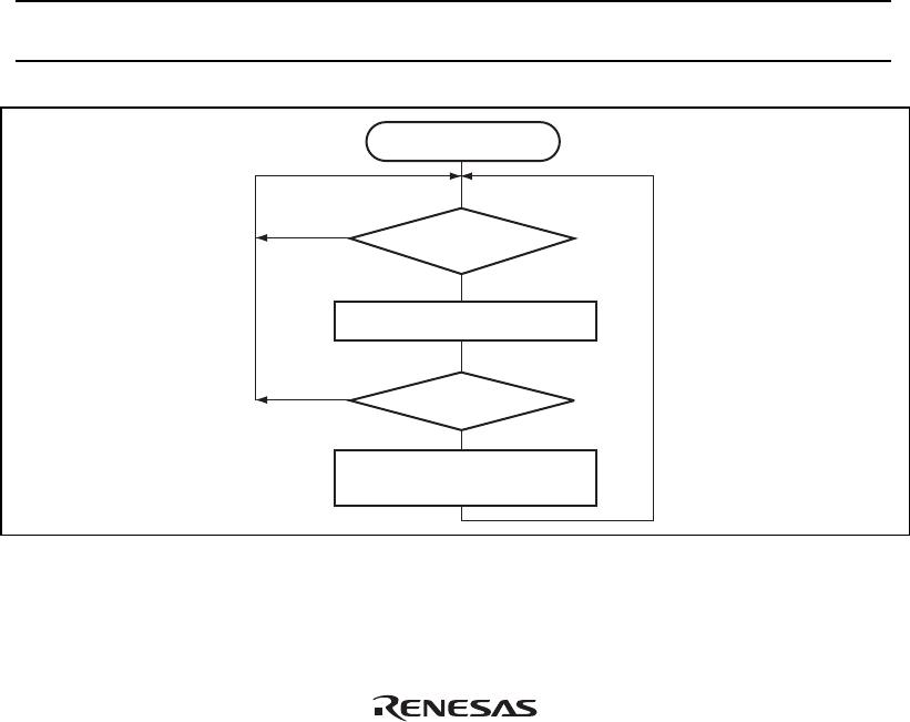
GA20 (P81). Figure 15.4 shows the GA20 output in flowchart form. Table 15.4 indicates the
GA20 output signal values.
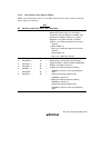
Table 15.3 GA20 (P81) Set/Clear Timing
Pin Name Setting Condition Clearing Condition
GA20 (P81) When bit 1 of the data that follows an
H'D1 host command is 1
When bit 1 of the data that follows an
H'D1 host command is 0
Start
Wait for next byte
H'D1 command
received?
Host write
Host write
Yes
No
Data byte?
No
Write bit 1 of data byte
to DR bit of P81/GA20
Yes
Figure 15.4 GA20 Output