


Rev. 1.00, 05/04, page 347 of 544
SASLA
R/W
SASLA
R/W A
DATA2
SASLA
R/W ASLA
R/W
A
DATA3
A
DATA4
DATA1
I
2
C bus interface
(Master transmit mode)
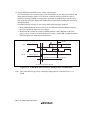
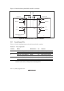
Transmit data match
Transmit timing match
• Receive address is ignored • Automatically transferred to slave
receive mode
• Receive data is recognized as an
address
• When the receive data matches to
the address set in the SAR or SARX
register, the I
2
C bus interface operates
as a slave device.
• Arbitration is lost
• The AL flag in ICSR is set to 1
Transmit data does not match
Other device
(Master transmit mode)
I
2
C bus interface
(Slave receive mode)
Data contention
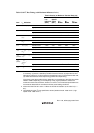
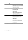
Figure 13.35 Diagram of Erroneous Operation when Arbitration is Lost
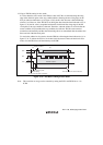
Though it is prohibited in the normal I
2
C protocol, the same problem may occur when the MST
bit is erroneously set to 1 and a transition to master mode is occurred during data transmission
or reception in slave mode. In multi-master mode, pay attention to the setting of the MST bit
when a bus conflict may occur. In this case, the MST bit in the ICCR register should be set to 1
according to the order below.
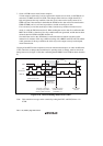
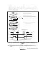
A. Make sure that the BBSY flag in the ICCR register is 0 and the bus is free before setting
the MST bit.
B. Set the MST bit to 1.
C. To confirm that the bus was not entered to the busy state while the MST bit is being set,
check that the BBSY flag in the ICCR register is 0 immediately after the MST bit has been
set.
Note: Above restriction can be cleared by setting bits FNC1 and FNC0 in the ICXR register.
13.6.1 Module Stop Mode Setting
The IIC operation can be enabled or disabled using the module stop control register. The initial
setting is for the IIC operation to be halted. Register access is enabled by canceling module stop
mode. For details, see section 20, Power-Down Modes.