


Rev. 1.00, 05/04, page 470 of 544
20.3 Medium-Speed Mode
The CPU makes a transition to medium-speed mode as soon as the current bus cycle ends
according to the setting of the SCK2 to SCK0 bits in SBYCR. In medium-speed mode, the CPU
operates on the operating clock (φ/2, φ/4, φ/8, φ/16, or φ/32). On-chip peripheral modules other
than the bus masters always operate on the system clock (φ).
In medium-speed mode, a bus access is executed in the specified number of states with respect to
the bus master operating clock. For example, if φ/4 is selected as the operating clock, on-chip
memory is accessed in 4 states, and internal I/O registers in 8 states.
By clearing all of bits SCK2 to SCK0 to 0, a transition is made to high-speed mode at the end of
the current bus cycle.
If a SLEEP instruction is executed when the SSBY bit in SBYCR is cleared to 0, and the LSON
bit in LPWRCR is cleared to 0, a transition is made to sleep mode. When sleep mode is cleared by
an interrupt, medium-speed mode is restored. When the SLEEP instruction is executed with the
SSBY bit set to 1, the LSON bit cleared to 0, and the PSS bit in TCSR (WDT_1) cleared to 0,
operation shifts to software standby mode. When software standby mode is cleared by an external
interrupt, medium-speed mode is restored.
When the RES pin is set low and medium-speed mode is cancelled, operation shifts to the reset
state. The same applies in the case of a reset caused by overflow of the watchdog timer.
When the STBY pin is driven low, medium-speed mode is cancelled and a transition is made to
hardware standby mode.
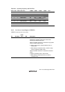
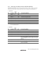
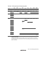
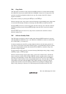
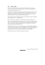
Figure 20.2 shows an example of medium-speed mode timing.
φ,
Bus master clock
peripheral module clock
Internal address bus
Internal write signal
Medium-speed mode
SBYCRSBYCR
Figure 20.2 Medium-Speed Mode Timing