


Rev. 1.00, 05/04, page 306 of 544
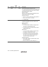
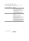
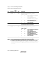
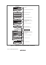
13.3.9 Port G Control Register (PGCTL)
PGCTL selects the input/output pin for IIC.
Bit Bit Name
Initial
Value R/W Description
7
6
IIC1BS
IIC1AS
0
0
R/W
R/W
IIC_1 Input/Output Select B, A
Selects input/output pins for IIC_1 channel
IIC1BS IIC1AS
0 0: Selects P42/SDA1 and P86/SCL1
as IIC_1 I/O pins
0 1: Selects PG4/ExSDAA and
PG5/ExSCLA as IIC_1 I/O pins*
1
1 0: Selects PG6/ExSDAB and
PG7/ExSCLB as IIC_1 I/O pins*
1
1 1: Setting prohibited*
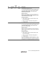
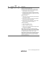
2
4, 5 All 0 R/W Reserved
The initial value should not be changed.
3
2
IIC0BS
IIC0AS
0
0
R/W
R/W
IIC_0 Input/Output Select B, A
Selects input/output pins for IIC_1 channel
IIC0BS IIC0AS
0 0: Selects P97/SDA0 and P52/SCL0
as IIC_0 I/O pins
0 1: Selects PG4/ExSDAA and
PG5/ExSCLA as IIC_0 I/O pins*
1
1 0: Selects PG6/ExSDAB and
PG7/ExSCLB as IIC_0 I/O pins*
1
1 1: Setting prohibited*
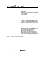
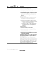
2
1, 0 All 0 R/W Reserved
The initial value should not be changed.
Notes: 1. The program development tool (emulator) does not support this function.
2. If multiple pins are selected as the serial clock I/O pin or serial data I/O pin for each
channel, the operation is not guaranteed. If a single pin is selected for both channels at
the same time, the operation is not guaranteed. When pins are switched, the I
2
C bus
must be free.