


Rev. 1.00, 05/04, page 433 of 544
18.2 Mode Transitions
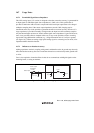
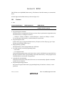
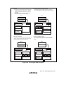
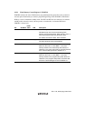
When the mode pins are set in the reset state and a reset-start is executed, this LSI enters an
operating mode as shown in figure 18.2. In user mode, flash memory can be read but not
programmed or erased. The boot, user program, and programmer modes are provided as modes to
write and erase the flash memory.
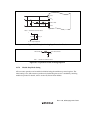
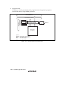
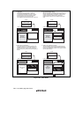
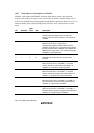
The differences between boot mode and user program mode are shown in table 18.1. Figure 18.3
shows the boot mode and figure 18.4 shows the user program mode.
RES = 0
RES = 0
FLSHE = 1
SWE = 1
FLSHE = 0
SWE = 0
*
1
*
2
RES = 0
MD1 = 1
RES = 0
Boot mode
On-board programming mode
User
program
mode
User mode
(on-chip ROM
enabled)
Reset state
Programmer
mode
Notes: Only make a transition between user mode
and user program mode when the CPU is not
accessing the flash memory.
1. MD1 = MD0 = 0, P92 = P91 = P90 = 1
2. MD1 = MD0 = 0, P92 = 0, P91 = P90 = 1
Figure 18.2 Flash Memory State Transitions
Table 18.1 Differences between Boot Mode and User Program Mode
Boot Mode User Program Mode
Total erase Yes Yes
Block erase No Yes
Programming control program* Program/program-verify Program/program-verify
Erase/erase-verify
Note: * Should be provided by the user, in accordance with the recommended algorithm.