


Rev. 1.00, 05/04, page 194 of 544
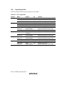
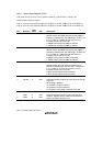
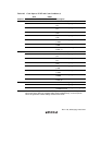
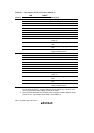
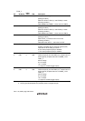
Table 10.3 Clock Input to TCNT and Count Condition (2)
TCR TCRXY*
2
Channel CKS2 CKS1 CKS0 CKSX CKSY Description
TMR_Y 0 0 0 — 0 Disables clock input
0 0 1 — 0 Increments at φ/4
0 1 0 — 0 Increments at φ/256
0 1 1 — 0 Increments at φ/2048
1 0 0 — 0 Disables clock input
0 0 0 — 1 Disables clock input
0 0 1 — 1 Increments at φ/4096
0 1 0 — 1 Increments at φ/8192
0 1 1 — 1 Increments at φ/16384
1 0 0 — 1 Increments at overflow signal from
TCNT_X*
1
1 0 1 — — Increments at rising edge of external
clock
1 1 0 — — Increments at falling edge of external
clock
1 1 1 — — Increments at both rising and falling
edges of external clock
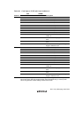
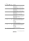
TMR_X 0 0 0 0 — Disables clock input
0 0 1 0 — Increments at φ
0 1 0 0 — Increments at φ/2
0 1 1 0 — Increments at φ/4
1 0 0 0 — Disables clock input
0 0 0 1 — Disables clock input
0 0 1 1 — Increments at φ/2048
0 1 0 1 — Increments at φ/4096
0 1 1 1 — Increments at φ/8192
1 0 0 1 — Increments at compare-match A from
TCNT_Y*
1
1 0 1 — — Increments at rising edge of external
clock
1 1 0 — — Increments at falling edge of external
clock
1 1 1 — — Increments at both rising and falling
edges of external clock
Notes: 1. If the TMR_Y clock input is set as the TCNT_X overflow signal and the TMR_X clock
input is set as the TCNT_Y compare-match signal simultaneously, a count-up clock
cannot be generated. These settings should not be made.
2. The program development tool (emulator) does not support TCRXY. Selection of the
internal clock is only available when CKSX = 0 and CKSY = 0.