Rev. 1.00, 05/04, page 427 of 544
AV
CC
*
1
AN0 to AN5
AV
SS
Notes: Values are reference values.
2. R
in
: Input impedance
1.
*
1
R
in
*
2
100 Ω
0.1 µF
0.01 µF10 µF
AV
ref
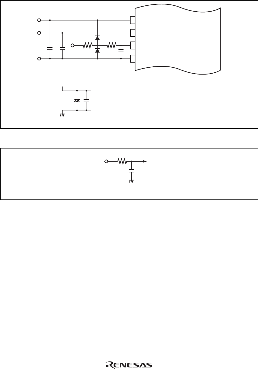
Figure 16.8 Example of Analog Input Protection Circuit
20 pF
To A/D converterAN0 to AN5
10 k
Ω
Note: * Values are reference values.
Figure 16.9 Equivalent Circuit of Analog Input Pin
16.7.6 Module Stop Mode Setting
A/D converter operation can be enabled or disabled using the module stop control register. The
initial setting is for A/D converter operation to be halted. Register access is enabled by canceling
module stop mode. For details, refer to section 20, Power-Down Modes.


