


Rev. 1.00, 05/04, page 320 of 544
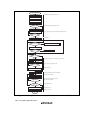
12. The IRIC flag is set to 1 in either of the following cases.
At the fall of the 8th receive clock pulse for one frame
SCL is automatically fixed low in synchronization with the internal clock until the IRIC
flag is cleared.
At the rise of the 9th receive clock pulse for one frame
The IRTR and ICDRF flags are set to 1, indicating that one frame of data has been
received. The master device outputs the receive clock continuously to receive the next data.
13. Read the IRTR flag in ICSR.
If the IRTR flag is 0, execute step [14] to clear the IRIC flag to 0 to release the wait state.
If the IRTR flag is 1 and data reception is complete, execute step [15] to issue the stop
condition.
14. If IRTR flag is 0, clear the IRIC flag to 0 to release the wait state.
Execute step [12] to read the IRIC flag to detect the end of reception.
15. Clear the WAIT bit in CMR to cancel the wait mode.
Then, clear the IRIC flag. Clearing of the IRIC flag should be done while WAIT = 0. (If the
WAIT bit is cleared to 0 after clearing the IRIC flag and then an instruction to issue a stop
condition is executed, the stop condition may not be issued correctly.)
16. Read the last ICDR receive data.
17. Clear the BBSY bit and SCP bit to 0 in ICCR. This changes SDA from low to high when SCL
is high, and generates the stop condition.
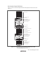
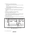
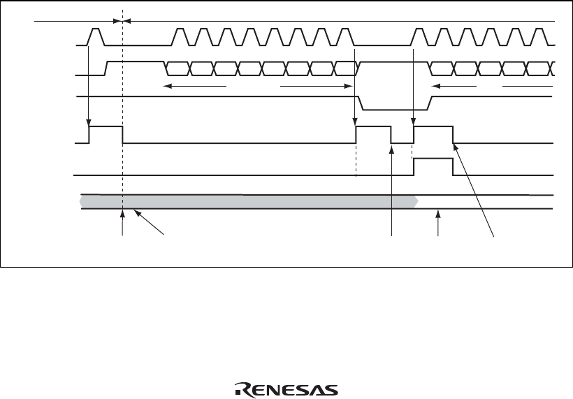
SDA
(master output)
SDA
(slave output)
21 214365879
Bit 7 Bit 6 Bit 7 Bit 6Bit 5 Bit 4 Bit 3 Bit 2 Bit 1 Bit 0
IRIC
IRTR
ICDR
SCL
(master output)
Data 1
[1] TRS cleared to 0
IRIC cleard to 0
[6] IRIC clear
[5] ICDR read
(Data 1)
[6] IRIC clear
(to end wait insertion)
User processing
Bit 5
Bit 4 Bit 3
543
9
Data 1
Data 2
[3] [3]
A
[2] ICDR read
(dummy read)
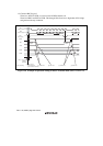
Master tansmit mode Master receive mode
A
[4]IRTR=0
[4] IRTR=1
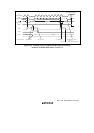
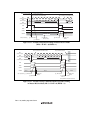
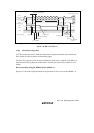
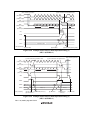
Figure 13.15 Example of Master Receive Mode Operation Timing
(MLS = ACKB = 0, WAIT = 1)