


Rev. 1.00, 05/04, page 417 of 544
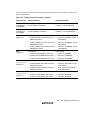
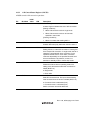
16.3.2 A/D Control/Status Register (ADCSR)
ADCSR controls A/D conversion operations.
Bit Bit Name
Initial
Value R/W Description
7 ADF 0 R/(W)* A/D End Flag
A status flag that indicates the end of A/D conversion.
[Setting conditions]
• When A/D conversion ends in single mode
• When A/D conversion ends on all channels
specified in scan mode
[Clearing conditions]
• When 0 is written after reading ADF = 1
6 ADIE 0 R/W A/D Interrupt Enable
Enables ADI interrupt by ADF when this bit is set to 1
5 ADST 0 R/W A/D Start
Setting this bit to 1 starts A/D conversion. Clearing this
bit to 0 stops A/D conversion. In single mode, this bit is
cleared to 0 automatically when conversion on the
specified channel ends. In scan mode, conversion
continues sequentially on the specified channels until
this bit is cleared to 0 by software, a reset, or a
transition to standby mode or module stop mode.
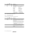
4 SCAN 0 R/W Scan Mode
Selects the A/D conversion operating mode. The
setting of this bit must be made when conversion is
halted (ADST = 0).
0: Single mode
1: Scan mode
3 CKS 0 R/W Clock Select
Sets A/D conversion time. The input channel setting
must be made when conversion is halted (ADST = 0).
0: Conversion time is 266 states (max)
1: Conversion time is 134 states (max)
Switch conversion time while ADST is 0.