


Rev. 1.00, 05/04, page 268 of 544
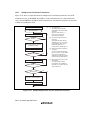
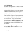
12.6.4 Serial Data Reception (Clocked Synchronous Mode)
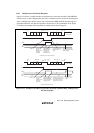
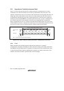
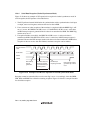
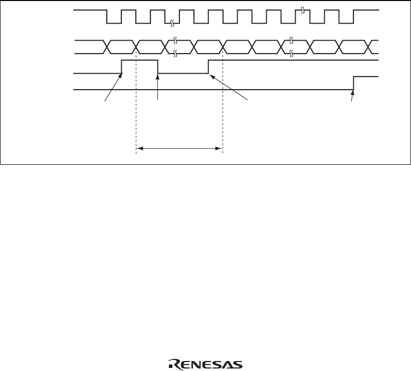
Figure 12.18 shows an example of SCI operation for reception in clocked synchronous mode. In
serial reception, the SCI operates as described below.
1. The SCI performs internal initialization in synchronization with a synchronization clock input
or output, starts receiving data, and stores the receive data in RSR.
2. If an overrun error (when reception of the next data is completed while the RDRF flag is still
set to 1) occurs, the ORER bit in SSR is set to 1. If the RIE bit in SCR is set to 1 at this time,
an ERI interrupt request is generated. Receive data is not transferred to RDR. The RDRF flag
remains to be set to 1.
3. If reception finishes successfully, the RDRF bit in SSR is set to 1, and receive data is
transferred to RDR. If the RIE bit in SCR is set to 1 at this time, an RXI interrupt request is
generated. Because the RXI interrupt routine reads the receive data transferred to RDR before
reception of the next receive data has finished, continuous reception can be enabled.
Bit 7
Serial data
Synchronization
clock
1 frame
RDRF
ORER
ERI interrupt request
generated by overrun
error
RXI interrupt
request generated
RDR data read and
RDRF flag cleared
to 0 in RXI interrupt
handling routine
RXI interrupt
request
generated
Bit 0 Bit 7 Bit 0 Bit 1 Bit 6 Bit 7
Figure 12.18 Example of SCI Receive Operation in Clocked Synchronous Mode
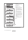
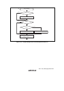
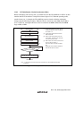
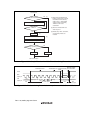
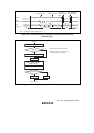
Reception cannot be resumed while a receive error flag is set to 1. Accordingly, clear the ORER,
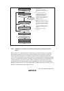
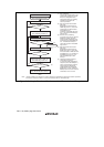
FER, PER, and RDRF bits to 0 before resuming reception. Figure 12.19 shows a sample flowchart
for serial data reception.