


Rev. 1.00, 05/04, page 418 of 544
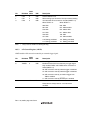
Bit Bit Name
Initial
Value R/W Description
Channel Select 2 to 0
Select analog input channels. The input channel setting
must be made when conversion is halted (ADST = 0).
2
1
0
CH2
CH1
CH0
0
0
0
R/W
R/W
R/W
When SCAN = 0:
000: AN0
001: AN1
010: AN2
011: AN3
100: AN4
101: AN5
110: Setting prohibited
111: Setting prohibited
When SCAN = 1:
000: AN0
001: AN0 and AN1
010: AN0 to AN2
011: AN0 to AN3
100: AN4
101: AN4 and AN5
110: Setting prohibited
111: Setting prohibited
Note: * Only 0 can be written for clearing the flag.
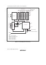
16.3.3 A/D Control Register (ADCR)
ADCR enables A/D conversion started by an external trigger signal.
Bit Bit Name
Initial
Value R/W Description
7
6
TRGS1
TRGS0
0
0
R/W
R/W
Timer Trigger Select 1 and 0
Enable the start of A/D conversion by a trigger signal.
Only set bits TRGS1 and TRGS0 when conversion is
halted (ADST = 0).
00: A/D conversion start by external trigger is disabled
01: A/D conversion start by external trigger is disabled
10: A/D conversion start by conversion trigger from
TMR is enabled
11: A/D conversion start by ADTRG pin is enabled
5 to 0 — All 1 R Reserved
These bits are always read as 1 and cannot be
modified.