


Rev. 1.00, 05/04, page 449 of 544
End of erasing
START
Set SWE bit in FLMCR1
Set ESU bit in FLMCR2
Set E bit in FLMCR1
Wait (x) µs
Wait (y) µs
n = 1
Set EBR1 and EBR2
Enable WDT
*
4
*
2
*
2
*
2
*
2
*
2
*
2
*
2
*
2
*
2
*
2
Wait (z) ms
Wait (α) µs
Wait (β) µs
Wait (γ) µs
Set block start address
as verify address
Wait (ε) µs
Wait (η) µs
*
5
*
3
Start of erasing
Clear E bit in FLMCR1
Clear ESU bit in FLMCR2
Set EV bit in FLMCR1
H'FF dummy write to verify address
Read verify data
Clear EV bit in FLMCR1
Wait (η) µs
Clear EV bit in FLMCR1
Clear SWE bit in FLMCR1
Disable WDT
End of erasing
*
1
Verify data
= all "1"?
Last address
of block?
All erase blocks erased?
Erase failure
Clear SWE bit in FLMCR1
n≥ (N) ?
NG
NG
NG
NG
OK
OK
OK
OK
Increment
address
n ← n + 1
Wait (θ) µs
Wait (θ) µs
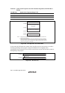
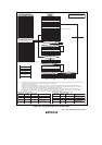
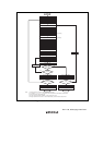
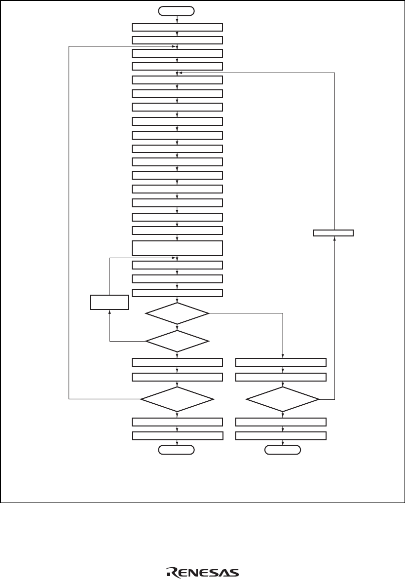
Notes: 1. Prewriting (writing 0 to all data in erased block) is not necessary.
2. The values of x, y, z, α, β, γ, ε, η, θ, and N are shown in section 22.5, Flash Memory Characteristics.
3. Verify data is read in 16-bit (word) units.
4. Set only a single bit in EBR1 and EBR2. Do not set more than one bit.
5. Erasing is performed in block units. To erase multiple blocks, each block must be erased in turn.
Figure 18.10 Erase/Erase-Verify Flowchart