


Rev. 1.00, 05/04, page 402 of 544
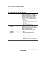
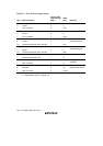
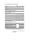
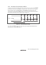
Table 15.5 shows the scope of the host interface pin shutdown.
Table 15.5 Scope of Host Interface Pin Shutdown
Abbreviation Port
Scope of
Shutdown I/O Notes
LAD3 to LAD0 P33–P30 O I/O Hi-Z
LFRAME P34 O Input Hi-Z
LRESET P35 × Input LPC hardware reset function is active
LCLK P36 O Input Hi-Z
SERIRQ P37 O I/O Hi-Z
LSCI PB1 ∆ I/O Hi-Z, only when LSCIE = 1
LSMI PB0 ∆ I/O Hi-Z, only when LSMIE = 1
PME P80 ∆ I/O Hi-Z, only when PMEE = 1
GA20 P81 ∆ I/O Hi-Z, only when FGA20E = 1
CLKRUN P82 O I/O Hi-Z
LPCPD P83 × Input Needed to clear shutdown state
[Legend]
O: Pin that is shutdown by the shutdown function
∆: Pin that is shutdown only when the LPC function is selected by register setting
×: Pin that is not shutdown
In the LPC shutdown state, the LPC's internal state and some register bits are initialized. The order
of priority of LPC shutdown and reset states is as follows.
1. System reset (reset by STBY or RES pin input, or WDT0 overflow)
All register bits, including bits LPC3E to LPC1E, are initialized.
2. LPC hardware reset (reset by LRESET pin input)
LRSTB, SDWNE, and SDWNB bits are cleared to 0.
3. LPC software reset (reset by LRSTB)
SDWNE and SDWNB bits are cleared to 0.
4. LPC hardware shutdown
SDWNB bit is cleared to 0.
5. LPC software shutdown