


Rev. 1.00, 05/04, page 289 of 544
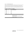
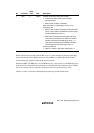
13.3.5 I
2
C Bus Control Register (ICCR)
ICCR controls the I
2
C bus interface and performs interrupt flag confirmation.
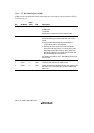
Bit Bit Name
Initial
Value R/W Description
7 ICE 0 R/W I
2
C Bus Interface Enable
0: I
2
C bus interface modules are stopped and I
2
C bus
interface module internal state is initialized. SAR and
SARX can be accessed.
1: I
2
C bus interface modules can perform transfer
operation, and the ports function as the SCL and SDA
input/output pins. ICMR and ICDR can be accessed.
6 IEIC 0 R/W I
2
C Bus Interface Interrupt Enable
0: Disables interrupts from the I
2
C bus interface to the
CPU
1: Enables interrupts from the I
2
C bus interface to the
CPU.
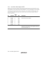
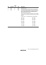
5
4
MST
TRS
0
0
R/W
R/W
Master/Slave Select
Transmit/Receive Select
MST TRS
0 0 : Slave receive mode
0 1 : Slave transmit mode
1 0 : Master receive mode
1 1 : Master transmit mode
Both these bits will be cleared by hardware when they
lose in a bus contention in master mode with the I
2
C bus
format. In slave receive mode with I
2
C bus format, the
R/W bit in the first frame immediately after the start
condition sets these bits in receive mode or transmit
mode automatically by hardware.
Modification of the TRS bit during transfer is deferred
until transfer is completed, and the changeover is made
after completion of the transfer.