Rev. 1.00, 05/04, page 207 of 544
10.5 Operation Timing
10.5.1 TCNT Count Timing
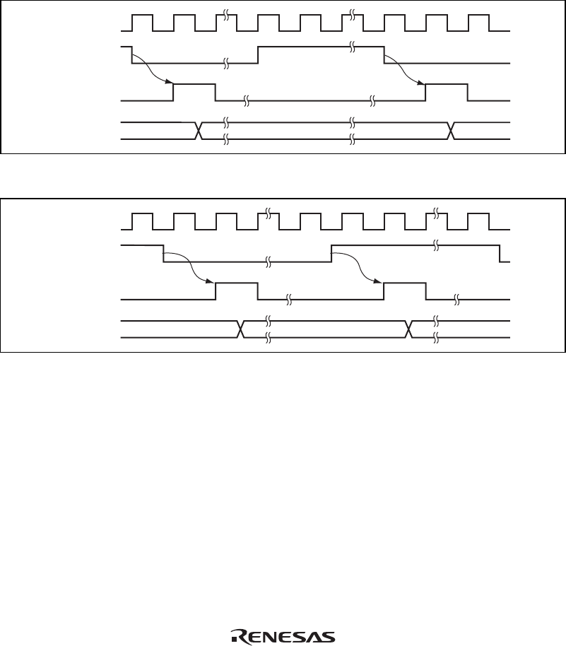
Figure 10.5 shows the TCNT count timing with an internal clock source. Figure 10.6 shows the
TCNT count timing with an external clock source. The pulse width of the external clock signal
must be at least 1.5 system clocks (φ) for a single edge and at least 2.5 system clocks (φ) for both
edges. The counter will not increment correctly if the pulse width is less than these values.
φ
Internal clock
TCNT input
clock
TCNT
N – 1 N N + 1
Figure 10.5 Count Timing for Internal Clock Input
φ
External clock
input pin
TCNT input
clock
TCNT
N – 1 N
N + 1
Figure 10.6 Count Timing for External Clock Input (Both Edges)
10.5.2 Timing of CMFA and CMFB Setting at Compare-Match
The CMFA and CMFB flags in TCSR are set to 1 by a compare-match signal generated when the
TCNT and TCOR values match. The compare-match signal is generated at the last state in which
the match is true, just when the timer counter is updated. Therefore, when TCNT and TCOR
match, the compare-match signal is not generated until the next TCNT input clock. Figure 10.7
shows the timing of CMF flag setting.


