


Rev. 1.00, 05/04, page 420 of 544
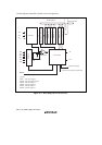
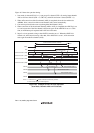
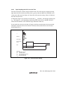
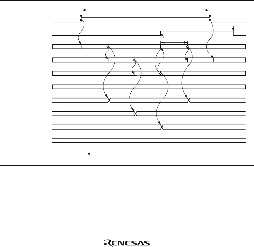
Figure 16.2 shows the operation timing.
1. Scan mode is selected (SCAN = 1), scan group 0 is selected (CH2 = 0), analog input channels
AN0 to AN2 are selected (CH1 = 1, CH0 = 0), and A/D conversion is started (ADST = 1).
2. When A/D conversion of the first channel (AN0) is completed, the result is transferred to
ADDRA. Next, conversion of the second channel (AN1) starts automatically.
3. Conversion proceeds in the same way through the third channel (AN2).
4. When conversion of all the selected channels (AN0 to AN2) is completed, the ADF flag is set
to 1 and conversion of the first channel (AN0) starts again. If the ADIE bit is set to 1 at this
time, an ADI interrupt is requested after A/D conversion ends.
5. Steps 2 to 4 are repeated as long as the ADST bit remains set to 1. When the ADST bit is
cleared to 0, A/D conversion stops. After that, if the ADST bit is set to 1, A/D conversion
starts again from the first channel (AN0).
ADST
ADF
ADDRA
ADDRB
ADDRC
ADDRD
State of channel 0 (AN0)
State of channel 1 (AN1)
State of channel 2 (AN2)
State of channel 3 (AN3)
Set*
1
Clear*
1
Idle
Notes: 1. Vertical arrows ( ) indicate instructions executed by software.
2. Data currently being converted is ignored.
Clear*
1
Idle
Idle
A/D conversion time
Idle
Continuous A/D conversion execution
A/D conversion 1
Idle Idle
Idle
Idle
Idle
Transfer
*
2
A/D conversion 3
A/D conversion 2 A/D conversion 5
A/D conversion 4
A/D conversion result 1
A/D conversion result 2
A/D conversion result 3
A/D conversion result 4
Figure 16.2 Example of A/D Converter Operation
(Scan Mode, Channels AN0 to AN2 Selected)