


Rev. 1.00, 05/04, page 379 of 544
15.3.3 LPC Channel 3 Address Register (LADR3)
LADR3 comprises two 8-bit readable/writable registers that perform LPC channel-3 host address
setting and control the operation of the bidirectional data registers. The contents of the address
field in LADR3 must not be changed while channel 3 is operating (while LPC3E is set to 1).
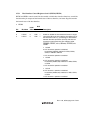
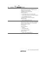
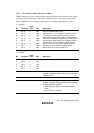
• LADR3H
Bit Bit Name
Initial
Value R/W Description
7
6
5
4
3
2
1
0
Bit 15
Bit 14
Bit 13
Bit 12
Bit 11
Bit 10
Bit 9
Bit 8
0
0
0
0
0
0
0
0
R/W
R/W
R/W
R/W
R/W
R/W
R/W
R/W
Channel 3 Address Bits 15 to 8:
When LPC3E = 1, an I/O address received in an LPC
I/O cycle is compared with the contents of LADR3.
When determining an IDR3, ODR3, or STR3 address
match, bit 0 of LADR3 is regarded as 0, and the value of
bit 2 is ignored. When determining a TWR0 to TWR15
address match, bit 4 of LADR3 is inverted, and the
values of bits 3 to 0 are ignored. Register selection
according to the bits ignored in address match
determination is as shown in table 15.2.
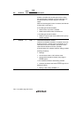
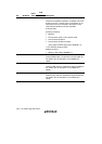
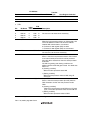
• LADR3L
Bit Bit Name
Initial
Value R/W Description
7
6
5
4
3
Bit 7
Bit 6
Bit 5
Bit 4
Bit 3
0
0
0
0
0
R/W
R/W
R/W
R/W
R/W
Channel 3 Address Bits 7 to 3
2 0 R/W Reserved
This bit is readable/writable, however, only 0 should be
written to this bit.
1 Bit 1 0 R/W Channel 3 Address Bit 1
0 TWRE 0 R/W Bidirectional Data Register Enable
Enables or disables bidirectional data register operation.
0: TWR operation is disabled
TWR-related I/O address match determination is
halted
1: TWR operation is enabled