


Rev. 1.00, 05/04, page 254 of 544
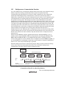
12.4.5 Data Transmission (Asynchronous Mode)
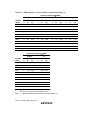
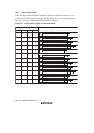
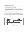
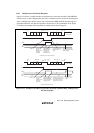
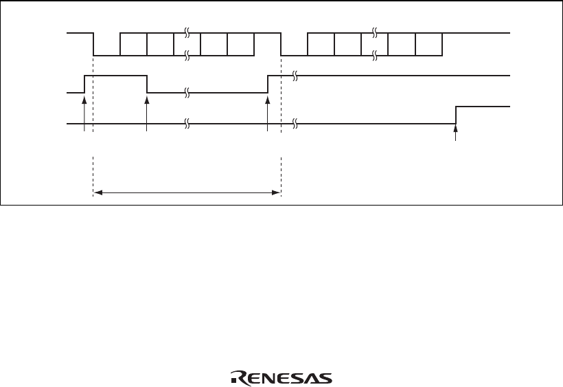
Figure 12.6 shows an example of the operation for transmission in asynchronous mode. In
transmission, the SCI operates as described below.
1. The SCI monitors the TDRE flag in SSR, and if it is cleared to 0, recognizes that data has been
written to TDR, and transfers the data from TDR to TSR.
2. After transferring data from TDR to TSR, the SCI sets the TDRE flag to 1 and starts
transmission. If the TIE bit in SCR is set to 1 at this time, a transmit data empty interrupt
request (TXI) is generated. Because the TXI interrupt routine writes the next transmit data to
TDR before transmission of the current transmit data has finished, continuous transmission can
be enabled.
3. Data is sent from the TxD pin in the following order: start bit, transmit data, parity bit or
multiprocessor bit (may be omitted depending on the format), and stop bit.
4. The SCI checks the TDRE flag at the timing for sending the stop bit.
5. If the TDRE flag is 0, the data is transferred from TDR to TSR, the stop bit is sent, and then
serial transmission of the next frame is started.
6. If the TDRE flag is 1, the TEND flag in SSR is set to 1, the stop bit is sent, and then the “mark
state” is entered in which 1 is output. If the TEIE bit in SCR is set to 1 at this time, a TEI
interrupt request is generated.
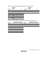
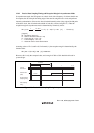
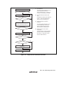
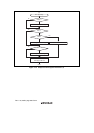
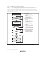
Figure 12.7 shows a sample flowchart for transmission in asynchronous mode.
TDRE
TEND
0
1 frame
D0 D1 D7 0/1 1 0 D0 D1
D7
0/1 1
1
1
DataStart
bit
Parity
bit
Stop
bit
Start
bit
Data Parity
bit
Stop
bit
TXI interrupt
request generated
Data written to TDR and
TDRE flag cleared to 0 in
TXI interrupt handling routine
TEI interrupt
request generated
Idle state
(mark state)
TXI interrupt
request generated
Figure 12.6 Example of SCI Transmit Operation in Asynchronous Mode (Example with 8-
Bit Data, Parity, One Stop Bit)