


Rev. 1.00, 05/04, page 473 of 544
20.6 Hardware Standby Mode
The CPU makes a transition to hardware standby mode from any mode when the STBY pin is
driven low.
In hardware standby mode, all functions enter the reset state. As long as the prescribed voltage is
supplied, on-chip RAM data is retained. The I/O ports are set to the high-impedance state.
In order to retain on-chip RAM data, the RAME bit in SYSCR should be cleared to 0 before
driving the STBY pin low. Do not change the state of the mode pins (MD1 and MD0) while this
LSI is in hardware standby mode.
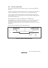
Hardware standby mode is cleared by the STBY pin input or the RES pin input.
When the STBY pin is driven high while the RES pin is low, clock oscillation is started. Ensure
that the RES pin is held low until system clock oscillation stabilizes. When the RES pin is
subsequently driven high after the clock oscillation stabilization time has passed, reset exception
handling starts.
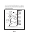
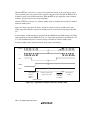
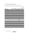
Figure 20.4 shows an example of hardware standby mode timing.
Oscillator
RES
STBY
Oscillation
stabilization
time
Reset
exception
handling
Figure 20.4 Hardware Standby Mode Timing