


Rev. 1.00, 05/04, page 210 of 544
10.6 TMR_0 and TMR_1 Cascaded Connection
If bits CKS2 to CKS0 in either TCR_0 or TCR_1 are set to B'100, the 8-bit timers of the two
channels are cascaded. With this configuration, the 16-bit count mode or compare-match count
mode is available.
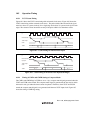
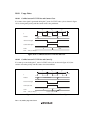
10.6.1 16-Bit Count Mode
When bits CKS2 to CKS0 in TCR_0 are set to B'100, the timer functions as a single 16-bit timer
with TMR_0 occupying the upper 8 bits and TMR_1 occupying the lower 8 bits.
Setting of compare-match flags
The CMF flag in TCSR_0 is set to 1 when a 16-bit compare-match occurs.
The CMF flag in TCSR_1 is set to 1 when a lower 8-bit compare-match occurs.
Counter clear specification
If the CCLR1 and CCLR0 bits in TCR_0 have been set for counter clear at compare-match,
the 16-bit counter (TCNT_0 and TCNT_1 together) is cleared when a 16-bit compare-
match occurs. The 16-bit counter (TCNT_0 and TCNT_1 together) is also cleared when
counter clear by the TMI0 pin has been set.
The settings of the CCLR1 and CCLR0 bits in TCR_1 are ignored. The lower 8 bits cannot be
cleared independently.
Pin output
Control of output from the TMO0 pin by bits OS3 to OS0 in TCSR_0 is in accordance with
the 16-bit compare-match conditions.
Control of output from the TMO1 pin by bits OS3 to OS0 in TCSR_1 is in accordance with
the lower 8-bit compare-match conditions.
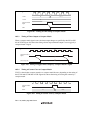
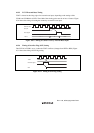
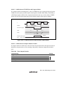
10.6.2 Compare-Match Count Mode
When bits CKS2 to CKS0 in TCR_1 are B'100, TCNT_1 counts the occurrence of compare-match
A for TMR_0. TMR_0 and TMR_1 are controlled independently. Conditions such as setting of the
CMF flag, generation of interrupts, output from the TMO pin, and counter clearing are in
accordance with the settings for each or TMR_0 and TMR_1.