


Rev. 1.00, 05/04, page 219 of 544
No.
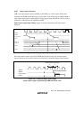
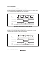
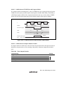
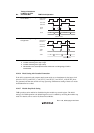
Timing of Switchover
by Means of CKS1
and CKS0 Bits
TCNT Clock Operation
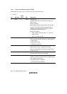
3 Clock switching from high
to low level∗
3
Clock before
switchover
Clock after
switchover
TCNT
clock
TCNT
CKS bit rewrite
N N + 1 N + 2
*
4
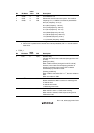
4 Clock switching from high
to high level
Clock before
switchover
Clock after
switchover
TCNT
clock
TCNT
CKS bit rewrite
N N + 1 N + 2
Notes: 1. Includes switching from low to stop, and from stop to low.
2. Includes switching from stop to high.
3. Includes switching from high to stop.
4. Generated on the assumption that the switchover is a falling edge; TCNT is
incremented.
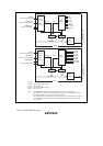
10.10.6 Mode Setting with Cascaded Connection
If the 16-bit count mode and compare-match count mode are set simultaneously, the input clock
pulses for TCNT_0 and TCNT_1, and TCNT_X and TCNT_Y and TCNT_A and TCNT_B are
not generated, and thus the counters will stop operating. Simultaneous setting of these two modes
should therefore be avoided.
10.10.7 Module Stop Mode Setting
TMR operation can be enabled or disabled using the module stop control register. The initial
setting is for TMR operation to be halted. Register access is enabled by canceling the module stop
mode. For details, refer to section 20, Power-Down Modes.