


Rev. 1.00, 05/04, page 197 of 544
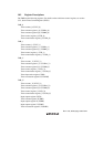
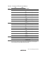
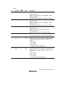
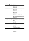
TCSR_1
Bit Bit Name
Initial
Value R/W Description
7 CMFB 0 R/(W)* Compare-Match Flag B
[Setting condition]
When the values of TCNT_1 and TCORB_1 match
[Clearing condition]
Read CMFB when CMFB = 1, then write 0 in CMFB
6 CMFA 0 R/(W)* Compare-Match Flag A
[Setting condition]
When the values of TCNT_1 and TCORA_1 match
[Clearing condition]
Read CMFA when CMFA = 1, then write 0 in CMFA
5 OVF 0 R/(W)* Timer Overflow Flag
[Setting condition]
When TCNT_1 overflows from H'FF to H'00
[Clearing condition]
Read OVF when OVF = 1, then write 0 in OVF
4 — 1 R Reserved
This bit is always read as 1 and cannot be modified.
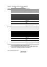
3
2
OS3
OS2
0
0
R/W
R/W
Output Select 3, 2
These bits specify how the TMO1 pin output level is to
be changed by compare-match B of TCORB_1 and
TCNT_1.
00: No change
01: 0 is output
10: 1 is output
11: Output is inverted (toggle output)
1
0
OS1
OS0
0
0
R/W
R/W
Output Select 1, 0
These bits specify how the TMO1 pin output level is to
be changed by compare-match A of TCORA_1 and
TCNT_1.
00: No change
01: 0 is output
10: 1 is output
11: Output is inverted (toggle output)
Note: * Only 0 can be written, for flag clearing.