


Rev. 1.00, 05/04, page 85 of 544
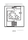
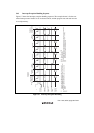
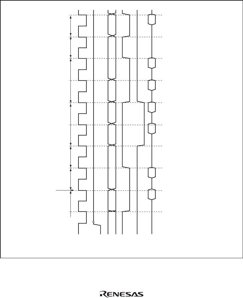
5.6.3 Interrupt Exception Handling Sequence
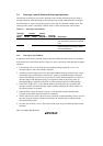
Figure 5.7 shows the interrupt exception handling sequence. The example shown is for the case
where interrupt control mode 0 is set in advanced mode, and the program area and stack area are
in on-chip memory.
(14)
(12)
(10)
(6)
(4)
(2)
(1) (5) (7) (9) (11) (13)
Prefetch of
instruction in
interrupt-handling
routine
Vector fetchStack access
Instruction
prefetch
Internal
processing
Internal
processing
Interrupt is
accepted
Interrupt level
decision and wait for
end of instruction
Interrupt
request signal
Internal
address bus
Internal read
signal
Internal write
signal
Internal
data bus
φ
(3)
(1)
(2) (4)
(3)
(5)
(7)
Instruction prefetch address (Instruction is not executed.
Address is saved as PC contents, becoming return address.)
Instruction code (not executed)
Instruction prefetch address (Instruction is not executed.)
SP – 2
SP – 4
Saved PC and CCR
Vector address
Starting address of interrupt-handling routine (contents of vector address)
Starting address of interrupt-handling routine ((13) = (10) (12))
First instruction in interrupt-handling routine
(6) (8)
(9) (11)
(10) (12)
(13)
(14)
(8)
Figure 5.7 Interrupt Exception Handling