


Rev. 1.00, 05/04, page 260 of 544
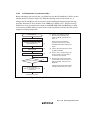
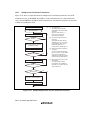
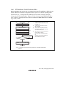
12.5.1 Multiprocessor Serial Data Transmission
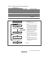
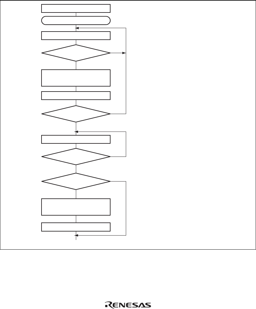
Figure 12.11 shows a sample flowchart for multiprocessor serial data transmission. For an ID
transmission cycle, set the MPBT bit in SSR to 1 before transmission. For a data transmission
cycle, clear the MPBT bit in SSR to 0 before transmission. All other SCI operations are the same
as those in asynchronous mode.
No
<End>
[1]
Yes
Initialization
Start transmission
Read TDRE flag in SSR [2]
Write transmit data to TDR and
set MPBT bit in SSR
No
Yes
No
Yes
Read TEND flag in SSR
[3]
No
Yes
[4]
Clear DR to 0 and set DDR to 1
Clear TE bit in SCR to 0
TDRE = 1
All data transmitted?
TEND = 1
Break output?
Clear TDRE flag to 0
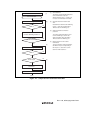
[1] SCI initialization:
The TxD pin is automatically
designated as the transmit data
output pin.
After the TE bit is set to 1, a
frame of 1s is output, and
transmission is enabled.
[2] SCI status check and transmit
data write:
Read SSR and check that the
TDRE flag is set to 1, then write
transmit data to TDR. Set the
MPBT bit in SSR to 0 or 1.
Finally, clear the TDRE flag to 0.
[3] Serial transmission continuation
procedure:
To continue serial transmission,
be sure to read 1 from the TDRE
flag to confirm that writing is
possible, then write data to TDR,
and then clear the TDRE flag to 0.
[4] Break output at the end of serial
transmission:
To output a break in serial
transmission, set port DDR to 1,
clear DR to 0, and then clear the
TE bit in SCR to 0.
Figure 12.11 Sample Multiprocessor Serial Transmission Flowchart