


Rev. 1.00, 05/04, page 301 of 544
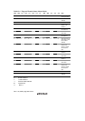
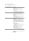
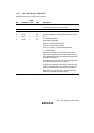
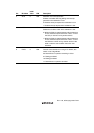
13.3.7 DDC Switch Register (DDCSWR)
DDCSWR controls IIC internal latch clearance.
Bit Bit Name
Initial
Value R/W Description
7 to 5 — All 0 R/W Reserved
The initial value should not be changed.
4 — 0 R Reserved
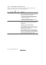
3
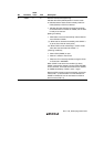
2
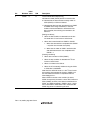
1
0
CLR3
CLR2
CLR1
CLR0
1
1
1
1
W*
W*
W*
W*
IIC Clear 3 to 0
Controls initialization of the internal state of IIC_0 and
IIC_1.
00--: Setting prohibited
0100: Setting prohibited
0101: IIC_0 internal latch cleared
0110: IIC_1 internal latch cleared
0111: IIC_0 and IIC_1 internal latches cleared
1---: Invalid setting
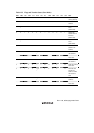
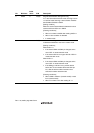
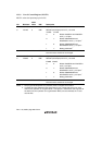
When a write operation is performed on these bits, a
clear signal is generated for the internal latch circuit of
the corresponding module, and the internal state of the
IIC module is initialized.
These bits can only be written to; they are always read
as 1. Write data to this bit is not retained.
To perform IIC clearance, bits CLR3 to CLR0 must be
written to simultaneously using an MOV instruction. Do
not use a bit manipulation instruction such as BCLR.
When clearing is required again, all the bits must be
written to in accordance with the setting.
Note: * This bit is always read as 1.