


Rev. 1.00, 05/04, page 238 of 544
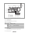
12.3.4 Transmit Shift Register (TSR)
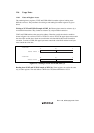
TSR is a shift register that transmits serial data. To perform serial data transmission, the SCI first
transfers transmit data from TDR to TSR, then sends the data to the TxD pin. TSR cannot be
directly accessed by the CPU.
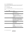
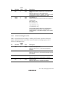
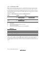
12.3.5 Serial Mode Register (SMR)
SMR is used to set the SCI's serial transfer format and select the on-chip baud rate generator clock
source.
Bit Bit Name
Initial
Value R/W Description
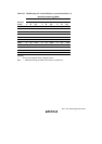
7 C/A 0 R/W Communication Mode
0: Asynchronous mode
1: Clocked synchronous mode
6 CHR 0 R/W Character Length (enabled only in asynchronous
mode)
0: Selects 8 bits as the data length.
1: Selects 7 bits as the data length. LSB-first is fixed
and the MSB of TDR is not transmitted in
transmission.
In clocked synchronous mode, a fixed data length of 8
bits is used.
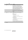
5 PE 0 R/W Parity Enable (enabled only in asynchronous mode)
When this bit is set to 1, the parity bit is added to
transmit data before transmission, and the parity bit is
checked in reception. For a multiprocessor format,
parity bit addition and checking are not performed
regardless of the PE bit setting.
4 O/E 0 R/W Parity Mode (enabled only when the PE bit is 1 in
asynchronous mode)
0: Selects even parity.
1: Selects odd parity.
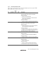
3 STOP 0 R/W Stop Bit Length (enabled only in asynchronous mode)
Selects the stop bit length in transmission.
0: 1 stop bit
1: 2 stop bits
In reception, only the first stop bit is checked. If the
second stop bit is 0, it is treated as the start bit of the
next transmit frame.