


Rev. 1.00, 05/04, page 274 of 544
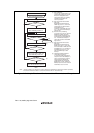
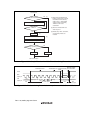
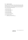
Start transmission
Transmission
[1]
No
No
No
Yes
Yes
Yes
Read TEND flag in SSR
Make transition to software standby mode etc.
Cancel software standby mode etc.
TE = 0
Initialization
TE = 1
[2]
[3]
All data transmitted?
Change operating mode?
TEND = 1
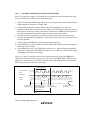
[1] Data being transmitted is lost
halfway. Data can be normally
transmitted from the CPU by
setting TE to 1, reading SSR,
writing to TDR, and clearing
TDRE to 0 after mode
cancellation.
[2] Also clear TIE and TEIE to 0
when they are 1.
[3] Module stop, watch, sub-active,
and sub-sleep modes are
included.
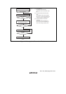
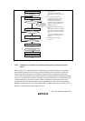
Figure 12.21 Sample Flowchart for Mode Transition during Transmission
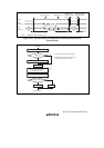
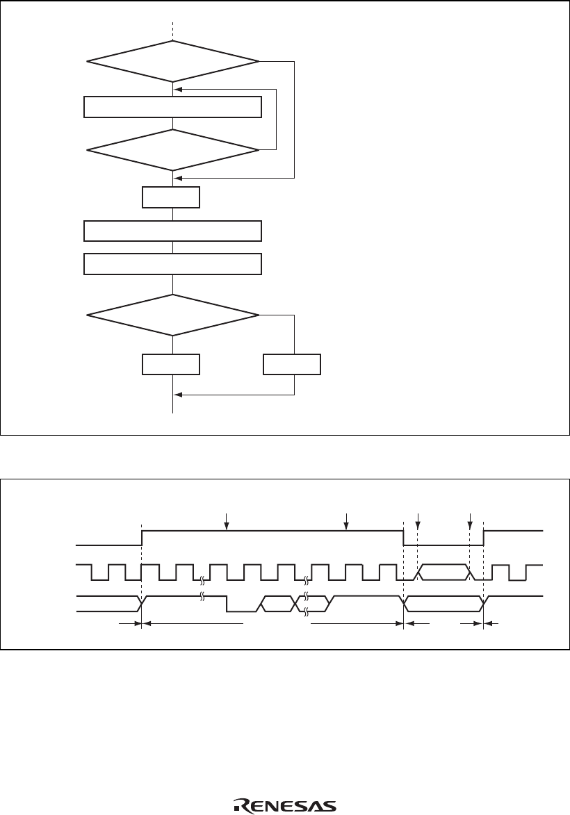
TE bit
SCK
output pin
TxD
output pin
Port
input/output
Port input/output
Port
input/output
Start Stop High outputHigh output
Transmission start
Transmission end
Transition to
software standby
mode
Software standby
mode cancelled
SCI TxD output
Port Port
SCI
TxD output
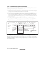
Figure 12.22 Pin States during Transmission in Asynchronous Mode (Internal Clock)