


Rev. 1.00, 05/04, page 244 of 544
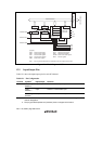
12.3.9 Bit Rate Register (BRR)
BRR is an 8-bit register that adjusts the bit rate. As the SCI performs baud rate generator control
independently for each channel, different bit rates can be set for each channel. Table 12.2 shows
the relationships between the N setting in BRR and bit rate B for normal asynchronous mode and
clocked synchronous mode. The initial value of BRR is H'FF, and it can be read from or written to
by the CPU at all times.
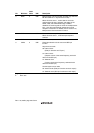
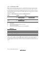
Table 12.2 Relationships between N Setting in BRR and Bit Rate B
Mode Bit Rate Error
Asynchronous mode
B =
64 × 2 × (N + 1)
2n-1
φ × 10
6
Error (%) = {
B × 64 × 2 × (N + 1)
2n-1
φ × 10
6
- 1 } × 100
Clocked synchronous
mode
B =
64 × 2 × (N + 1)
2n-1
φ × 10
6
—
[Legend]
B: Bit rate (bit/s)
N: BRR setting for baud rate generator (0 ≤ N ≤ 255)
φ: Operating frequency (MHz)
n: Determined by the SMR settings shown in the following table.
SMR Setting
CKS1 CKS0 n
0 0 0
0 1 1
1 0 2
1 1 3
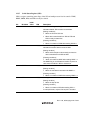
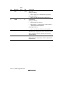
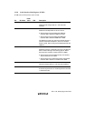
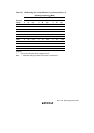
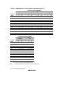
Table 12.3 shows sample N settings in BRR in normal asynchronous mode. Table 12.4 shows the
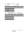
maximum bit rate settable for each frequency. Table 12.6 shows sample N settings in BRR in
clocked synchronous mode. Tables 12.5 and 12.7 show the maximum bit rates with external clock
input.