


Rev. 1.00, 05/04, page 280 of 544
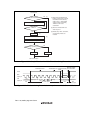
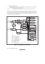
13.2 Input/Output Pins
Table 13.1 summarizes the input/output pins used by the I
2
C bus interface. The serial clock I/O pin
for each channel can be selected from the three pins*. The serial data I/O pin for each channel can
be selected form the three pins*. Do not set multiple pins as the serial clock I/O pin or serial data
I/O pin for a single channel.
Note: * The program development tool (emulator) does not support this function.
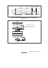
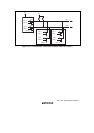
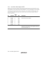
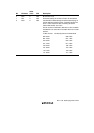
Table 13.1 Pin Configuration
Channel Symbol*
1
Input/Output Function
SCL0 Input/Output Serial clock input/output pin of IIC_0 0
SDA0 Input/Output Serial data input/output pin of IIC_0
SCL1 Input/Output Serial clock input/output pin of IIC_1 1
SDA1 Input/Output Serial data input/output pin of IIC_1
ExSCLA*
2
Input/Output Serial clock input/output pin of IIC_0 or IIC_1
ExSDAA*
2
Input/Output Serial data input/output pin of IIC_0 or IIC_1
ExSCLB*
2
Input/Output Serial clock input/output pin of IIC_0 or IIC_1
ExSDAB*
2
Input/Output Serial data input/output pin of IIC_0 or IIC_1
Notes: 1. In the text, the channel subscript is omitted, and only SCL and SDA are used.
2. The program development tool (emulator) does not support this function.