


xStack DGS-3600 Series Layer 3 Gigabit Ethernet Managed Switch CLI Manual
109
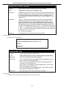
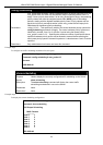
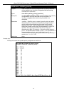
show bandwidth_control
numerical order. Non-contiguous portlist entries are separated by a comma. (ex:
1:1-1:3,1:7-1:9)
Restrictions None.
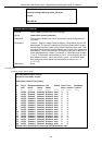
Example usage:
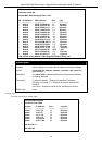
To display bandwidth control settings:
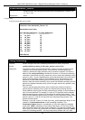
DGS-3600:4#show bandwidth_control 1-10
Command: show bandwidth_control 1-10
Bandwidth Control Table
Port RX Rate (64Kbit/sec) TX_Rate (64Kbit/sec)
---- ------------------------ ----------------------
1:1 no_limit 10
1:2 no_limit 10
1:3 no_limit 10
1:4 no_limit 10
1:5 no_limit 10
1:6 no_limit 10
1:7 no_limit 10
1:8 no_limit 10
1:9 no_limit 10
1:10 no_limit 10
DGS-3600:4#
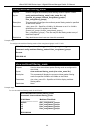
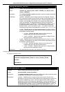
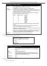
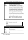
config scheduling
Purpose Used to configure the traffic scheduling mechanism for each COS queue.
Syntax
config scheduling <class_id 0-6> {max_packet <value 0-15>}
Description The Switch contains seven hardware priority queues. Incoming packets must be
mapped to one of these seven queues. This command is used to specify the
rotation by which these eight hardware priority queues are emptied. The Switch’s
default (if the config scheduling command is not used, or if the config scheduling
command is entered with the max_packet set to 0) is to empty the hardware priority
queues in order − from the highest priority queue (hardware queue 6) to the lowest
priority queue (hardware queue 0). Each hardware queue will transmit all of the
packets in its buffer before allowing the next lower priority queue to transmit its
packets. When the lowest hardware priority queue has finished transmitting all of its
packets, the highest hardware priority queue can again transmit any packets it may
have received.
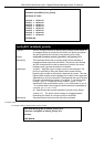
The max_packets parameter allows users to specify the maximum number of
packets a given hardware priority queue can transmit before allowing the next
lowest hardware priority queue to begin transmitting its packets. A value between 0
and 15 can be specified. For example, if a value of 3 is specified, then the highest
hardware priority queue (queue 6) will be allowed to transmit three packets − then
the next lowest hardware priority queue (number 5) will be allowed to transmit three
packets, and so on, until all of the queues have transmitted three packets. The
process will then repeat.
Entering a 0 into the <value 0-15> field of the max_packet parameter allows for the
creation of a Combination Queue for the forwarding of packets. This
Combination Queue allows for a combination of strict and weight-fair (weighted
round-robin “WRR”) scheduling. Priority classes that have a 0 in the max_packet
field will forward packets with strict priority scheduling. The remaining classes, that
do not have a 0 in their max_packet field, will follow a weighted round-robin (WRR)
method of forwarding packets — as long as the priority classes with a 0 in their