


AMD Geode™ SC2200 Processor Data Book 107
SuperI/O Module
32580B
5.4.2.3 LDN 02h - Infrared Communication Port or
Serial Port 3
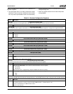
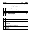
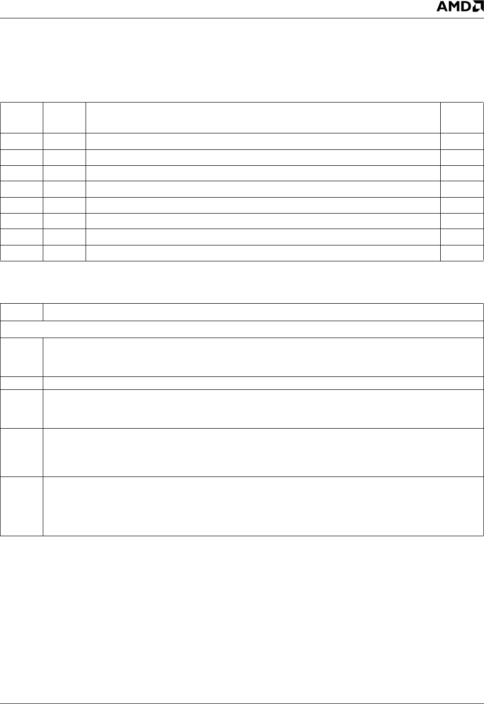
Table 5-9 lists the configuration registers which affect the
Infrared Communication Port or Serial Port 3 (IRCP/SP3).
Only the last register (F0h) is described here (Table 5-10).
See Table 5-3 "Standard Configuration Registers" on page
101 for descriptions of the other registers listed.
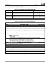
Table 5-9. Relevant IRCP/SP3 Registers
Index Type Configuration Register or Action
Reset
Value
30h R/W Activate. See also bit 0 of the SIOCF1 register. 00h
60h R/W Base Address MSB register. Bits [7:3] (for A[15:11]) are RO, 00000b. 03h
61h R/W Base Address LSB register. Bit [2:0] (for A[2:0]) are RO, 000b. E8h
70h R/W Interrupt Number. 00h
71h R/W Interrupt Type. Bit 1 is R/W; other bits are RO. 03h
74h R/W DMA Channel Select 0 (RX_DMA).04h
75h R/W DMA Channel Select 1 (TX_DMA). 04h
F0h R/W Infrared Communication Port/Serial Port 3 Configuration register. 02h
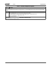
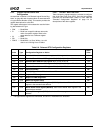
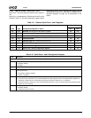
Table 5-10. IRCP/SP3 Configuration Register
Bit Description
Index F0h Infrared Communication Port/Serial Port 3 Configuration Register (R/W) Reset Value: 02h
7 Bank Select Enable. Enables bank switching.
0: All attempts to access the extended registers are ignored. (Default)
1: Enables bank switching.
6:3 Reserved.
2 Busy Indicator. (RO) This bit can be used by power management software to decide when to power-down the device.
0: No transfer in progress. (Default)
1: Transfer in progress.
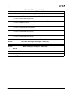
1 Power Mode Control. When the logical device is active in:
0: Low power mode - Clock disabled. The output signals are set to their default states. Registers are maintained. (Unlike
Active bit in Index 30h that also prevents access to device registers.)
1: Normal power mode - Clock enabled. The device is functional when the logical device is active. (Default)
0 TRI-STATE Control. When enabled and the device is inactive, the logical device output pins are in TRI-STATE. One excep-
tion is the IRTX/SOUT3 pin, which is driven to 0 when the Infrared Communication Port or Serial Port 3 is inactive and is not
affected by this bit.
0: Disabled. (Default)
1: Enabled (when the device is inactive).