


AMD Geode™ SC2200 Processor Data Book 345
Video Processor Module - Video Processor Registers - Function 4
32580B
8 CRT_HSYNC_POL (CRT Horizontal Synchronization Polarity). Selects CRT horizontal sync polarity.
0: CRT horizontal sync is normally low, and is set high during sync interval.
1: CRT horizontal sync is normally high, and is set low during sync interval.
7 FP_DATA_EN (Flat Panel Output Enable). Controls the data, data-enable, clock and sync output signals.
0: Flat panel data outputs are forced to zero depending on the value of bit 3 (DAC_BL_EN). Bit 6 (FP_PWR_EN) is
ignored.
1: Flat panel outputs are forced to zero until power-up, and later, data outputs are subject to the value of bit 3
(DAC_BL_EN).
6 FP_PWR_EN (Flat Panel Power Enable). Changing this bit initiates a flat panel power-up or power-down.
0-to-1: Power-up flat panel.
1-to-0: Power-down flat panel.
5:4 Reserved.
3 DAC_BL_EN (DAC Blank Enable). Controls blanking of the CRT DACs.
0: DACs are constantly blanked.
1: DACs are blanked normally (i.e., during horizontal and vertical blank).
2 VSYNC_EN (Vertical Sync Enable). Enables/disables display vertical sync (used for VESA DPMS support).
0: Disable.
1: Enable.
1 HSYNC_EN (Horizontal Sync Enable). Enables/disables display horizontal sync (used for VESA DPMS support).
0: Disable.
1: Enable.
0 CRT_EN (CRT Enable). Enables the CRT control logic. This bit is also used to reset the CRT control logic.
0: Reset CRT control logic.
1: Enable CRT control logic.
Offset 08h-0Bh Video X Position Register (R/W) Reset Value: 00000000h
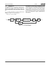
Provides the window X position. This register is programmed relative to CRT horizontal sync input (not physical screen position).
Note: H_TOTAL and H_SYNC_END are values programmed in the GX1 module’s Display Controller Timing registers
(GX_BASE+Memory Offset 8330h[26:19] and 8338h[10:3], respectively). The value of (H_TOTAL – H_SYNC_END) is some-
times referred to as “horizontal back porch”. For more information, see the GX1 Processor Series Data Book.
31:28 Reserved.
27:16 VID_X_END (Video X End Position). Represents the horizontal end position of the video window (not inclusive). This value
is calculated according to the following formula:
Value = Desired screen position + (H_TOTAL – H_SYNC_END) – 13.
15:12 Reserved.
11:0 VID_X_START (Video X Start Position). Represents the horizontal start position of the video window. This value is calcu-
lated according to the following formula:
Value = Desired screen position + (H_TOTAL – H_SYNC_END) – 14.
Offset 0Ch-0Fh Video Y Position Register (R/W) Reset Value: 00000000h
Provides the window Y position. This register is programmed relative to CRT vertical sync input (not physical screen position).
Note: V_TOTAL and V_SYNC_END are values programmed in the GX1 module’s Display Controller Timing registers
(GX_BASE+Memory Offset 8340h[26:16] and 8348h[26:16], respectively). The value of (V_TOTAL – V_SYNC_END) is some-
times referred to as “vertical back porch”. For more information, see the GX1 Processor Series Data Book.
31:27 Reserved.
26:16 VID_Y_END (Video Y End Position). Represents the vertical end position of the video window (not inclusive). This value is
calculated according to the following formula:
Value = Desired screen position + (V_TOTAL – V_SYNC_END) + 2.
15:11 Reserved
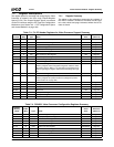
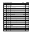
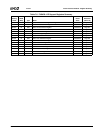
Table 7-7. F4BAR0+Memory Offset: Video Processor Configuration Registers (Continued)
Bit Description