


AMD Geode™ SC2200 Processor Data Book 389
Electrical Specifications
32580B
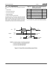
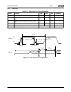
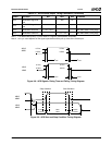
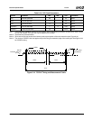
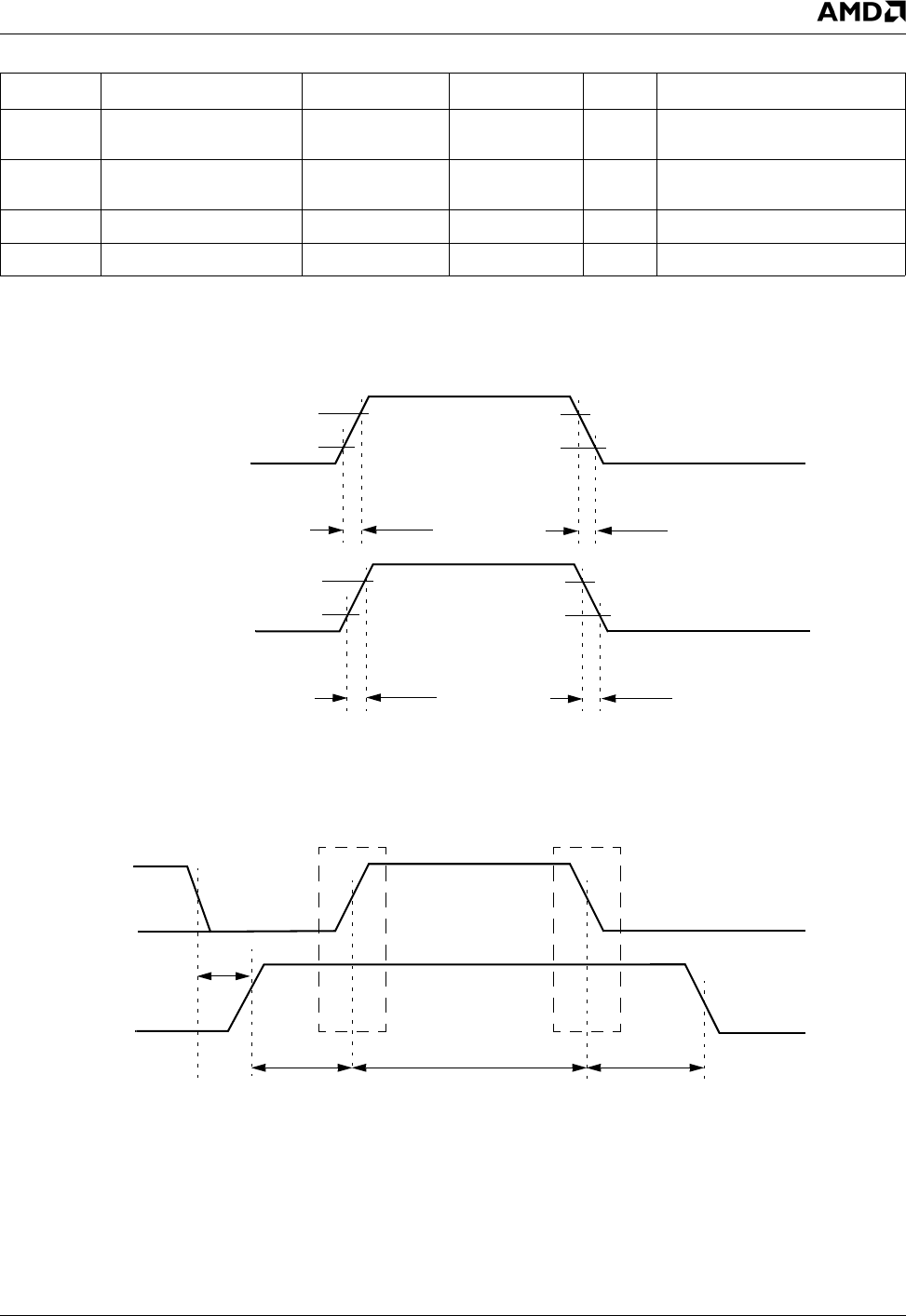
Figure 9-8. ACB Signals: Rising Time and Falling Timing Diagram
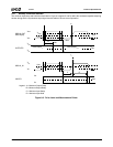
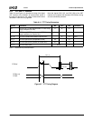
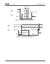
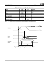
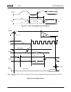
Figure 9-9. ACB Start and Stop Condition Timing Diagram
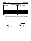
t
SDAfo
AB1D/AB2D signal fall
time
300 ns
t
SDAro
AB1D/AB2D signal rise
time
1 μs
t
SDAho
AB1D/AB2D hold time 7
*
t
CLK
- t
SCLfo
After AB1C/AB2C falling edge
t
SDAvo
AB1D/AB2D valid time 7
*
t
CLK
+ t
RD
After AB1C/AB2C falling edge
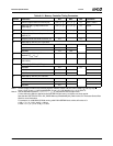
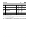
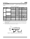
Note 1. K is determined by bits [7:1] of the ACBCTL2 register (LDN 05h/06h, Offset 05h).
Note 2. t
SCLhigho
value depends on the signal capacitance and the pull-up value of the relevant pin.
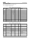
Table 9-17. ACCESS.bus Output Timing Parameters (Continued)
Symbol Parameter Min Max Unit Comments
AB1D
t
SDAr
0.7V
IO
0.3V
IO
t
SDAf
0.7V
IO
0.3V
IO
AB1C
t
SCLr
0.7V
IO
0.3V
IO
t
SCLf
0.7V
IO
0.3V
IO
AB2D
AB2C
AB1D
AB1C
t
CSTOsi
t
BUFi
t
DLCs
t
CSTRhi
Start Condition
Stop Condition
t
DLCo
t
CSTOso
t
BUFo
t
CSTRho
AB2D
AB2C