


AMD Geode™ SC2200 Processor Data Book 289
Core Logic Module - X-Bus Expansion Interface - Function 5
32580B
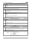
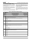
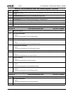
Index 44h-47h F5BAR1 Mask Address Register (R/W) Reset Value: 00000000h
To use F5BAR1, the mask register should be programmed first. The mask register defines the size of F5BAR1 and whether the
accessed offset registers are memory or I/O mapped. See F5 Index 40h (F5BAR0 Mask Address Register) above for bit descriptions.
Note: Whenever a value is written to this mask register, F5BAR1 must also be written (even if the value for F5BAR1 has not
changed).
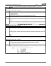
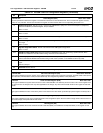
Index 48h-4Bh F5BAR2 Mask Address Register (R/W) Reset Value: 00000000h
To use F5BAR2, the mask register should be programmed first. The mask register defines the size of F5BAR2 and whether the
accessed offset registers are memory or I/O mapped. See F5 Index 40h (F5BAR0 Mask Address Register) above for bit descriptions.
Note: Whenever a value is written to this mask register, F5BAR2 must also be written (even if the value for F5BAR2 has not
changed).
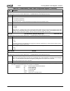
Index 4Ch-4Fh F5BAR3 Mask Address Register (R/W) Reset Value: 00000000h
To use F5BAR3, the mask register should be programmed first. The mask register defines the size of F5BAR3 and whether the
accessed offset registers are memory or I/O mapped. See F5 Index 40h (F5BAR0 Mask Address Register) above for bit descriptions.
Note: Whenever a value is written to this mask register, F5BAR3 must also be written (even if the value for F5BAR3 has not
changed).
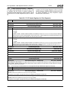
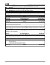
Index 50h-53h F5BAR4 Mask Address Register (R/W) Reset Value: 00000000h
To use F5BAR4, the mask register should be programmed first. The mask register defines the size of F5BAR4 and whether the
accessed offset registers are memory or I/O mapped. See F5 Index 40h (F5BAR0 Mask Address Register) above for bit descriptions.
Note: Whenever a value is written to this mask register, F5BAR4 must also be written (even if the value for F5BAR4 has not
changed).
Index 54h-57h F5BAR5 Mask Address Register (R/W) Reset Value: 00000000h
To use F5BAR5, the mask register should be programmed first. The mask register defines the size of F5BAR5 and whether the
accessed offset registers are memory or I/O mapped. See F5 Index 40h (F5BAR0 Mask Address Register) above for bit descriptions.
Note: Whenever a value is written to this mask register, F5BAR5 must also be written (even if the value for F5BAR5 has not
changed).
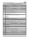
Index 58h F5BARx Initialized Register (R/W) Reset Value: 00h
7:6 Reserved. Must be set to 0.
5 F5BAR5 Initialized. This bit indicates if F5BAR5 (F5 Index 24h) has been initialized.
At reset this bit is cleared (0). Writing F5BAR5 sets this bit to 1. If this bit programmed to 0, the decoding of F5BAR5 is dis-
abled until either this bit is set to 1 or F5BAR5 is written (which causes this bit to be set to 1).
4 F5BAR4 Initialized. This bit indicates if F5BAR4 (F5 Index 28h) has been initialized.
At reset this bit is cleared (0). Writing F5BAR4 sets this bit to 1. If this bit programmed to 0, the decoding of F5BAR4 is dis-
abled until either this bit is set to 1 or F5BAR4 is written (which causes this bit to be set to 1).
3 F5BAR3 Initialized. This bit indicates if F5BAR3 (F5 Index 1Ch) has been initialized.
At reset this bit is cleared (0). Writing F5BAR3 sets this bit to 1. If this bit programmed to 0, the decoding of F5BAR3 is dis-
abled until either this bit is set to 1 or F5BAR3 is written (which causes this bit to be set to 1).
2 F5BAR2 Initialized. This bit indicates if F5BAR2 (F5 Index 18h) has been initialized.
At reset this bit is cleared (0). Writing F5BAR2 sets this bit to 1. If this bit programmed to 0, the decoding of F5BAR2 is dis-
abled until either this bit is set to 1 or F5BAR2 is written (which causes this bit to be set to 1).
1 F5BAR1 Initialized. This bit indicates if F5BAR1 (F5 Index 14h) has been initialized.
At reset this bit is cleared (0). Writing F5BAR1 sets this bit to 1. If this bit programmed to 0, the decoding of F5BAR1 is dis-
abled until either this bit is set to 1 or F5BAR1 is written (which causes this bit to be set to 1).
0
F5BAR0 Initialized. This bit indicates if F5BAR0 (F5 Index 10h) has been initialized.
At reset this bit is cleared (0). Writing F5BAR0 sets this bit to 1. If this bit programmed to 0, the decoding of F5BAR0 is dis-
abled until either this bit is set to 1 or F5BAR0 is written (which causes this bit to be set to 1).
Table 6-39. F5: PCI Header Registers for X-Bus Expansion (Continued)
Bit Description