


388 AMD Geode™ SC2200 Processor Data Book
Electrical Specifications
32580B
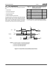
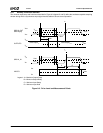
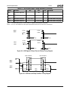
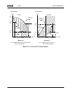
9.3.4 ACCESS.bus Interface
The following tables describe the timing for the ACCESS.bus signals.
Notes: 1) All ACCESS.bus timing is not 100% tested.
2) In this table t
CLK
= 1/24 MHz = 41.7 ns.
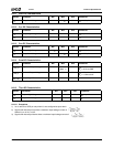
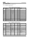
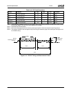
Table 9-16. ACCESS.bus Input Timing Parameters
Symbol Parameter Min Max Unit Comments
t
BUFi
Bus free time between
Stop and Start condition
t
SCLhigho
t
CSTOsi
AB1C/AB2C setup time 8
*
t
CLK
- t
SCLri
Before Stop condition
t
CSTRhi
AB1C/AB2C hold time 8
*
t
CLK
- t
SCLri
After Start condition
t
CSTRsi
AB1C/AB2C setup time 8
*
t
CLK
- t
SCLri
Before Start condition
t
DHCsi
Data high setup time 2
*
t
CLK
Before AB1C/AB2C rising edge
t
DLCsi
Data low setup time 2
*
t
CLK
Before AB1C/AB2C rising edge
t
SCLfi
AB1D/AB2D fall time 300 ns
t
SCLri
AB1D/AB2D rise time 1 μs
t
SCLlowi
AB1C/AB2C low time 16
*
t
CLK
After AB1C/AB2C falling edge
t
SCLhighi
AB1C/AB2C high time 16
*
t
CLK
After AB1C/AB2C rising edge
t
SDAfi
AB1D/AB2D fall time 300 ns
t
SDAri
AB1D/AB2D rise time 1 μs
t
SDAhi
AB1D/AB2D hold time 0 After AB1C/AB2C falling edge
t
SDAsi
AB1D/AB2D setup time 2
*
t
CLK
Before AB1C/AB2C rising edge
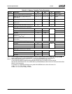
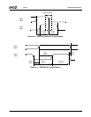
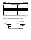
Table 9-17. ACCESS.bus Output Timing Parameters
Symbol Parameter Min Max Unit Comments
t
SCLhigho
AB1C/AB2C high time K
*
t
CLK
- 1 μs After AB1C/AB2C rising edge,
Note 1
t
SCLlowo
AB1C/AB2C low time K
*
t
CLK
- 1 μs After AB1C/AB2C falling edge
t
BUFo
Bus free time between
Stop and Start condition
t
SCLhigho
1 μs Note 2
t
CSTOso
AB1C/AB2C setup time t
SCLhigho
1 μs Before Stop condition, Note 2
t
CSTRho
AB1C/AB2C hold time t
SCLhigho
1 μs After Start condition, Note 2
t
CSTRso
AB1C/AB2C setup time t
SCLhigho
1 μs Before Start condition, Note 2
t
DHCso
Data high setup time t
SCLhigho
- t
SDAro
1 μs Before AB1C/AB2C rising
edge, Note 2
t
DLCso
Data low setup time t
SCLhigho
- t
SDAfo
1 μs Before AB1C/AB2C rising
edge, Note 2
t
SCLfo
AB1D/AB2D signal fall
time
300 ns
t
SCLro
AB1D/AB2D signal rise
time
1 μs