


AMD Geode™ SC2200 Processor Data Book 171
Core Logic Module
32580B
The automatic speedup events (video and IRQ) for Sus-
pend Modulation should be used together with software-
controlled speedup registers for major I/O events such as
any access to the FDC, HDD, or parallel/serial ports, since
these are indications of major system activities. When
major I/O events occur, Suspend Modulation should be
temporarily disabled using the procedures described in the
Power Management registers in the following subsections.
If a bus master (UltraDMA/33, Audio, USB) request occurs,
the GX1 module automatically de-asserts SUSPA# and
grants the bus to the requesting bus master. When the bus
master de-asserts REQ#, SUSPA# reasserts. This does
not directly affect the Suspend Modulation programming.
Configuring Suspend Modulation: Control of the Sus-
pend Modulation feature is accomplished using the Sus-
pend Modulation and Suspend Configuration registers (F0
Index 94h and 96h, respectively).
The Suspend Configuration register contains the global
power management enable bit, as well as the enables for
the individual activity speedup timers. The global power
management bit must be enabled for Suspend Modulation
and all other power management resources to function.
Bit 0 of the Suspend Configuration register enables Sus-
pend Modulation. Bit 1 controls how SMI events affect Sus-
pend Modulation. In general this bit should be set to 1,
which causes SMIs to disable Suspend Modulation until it
is re-enabled by the SMI handler.
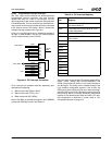
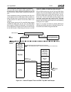
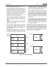
The Suspend Modulation register controls two 8-bit
counters that represent the number of 32 µs intervals that
the internal SUSP# signal is asserted and then de-
asserted to the GX1 module. These counters define a ratio
which is the effective frequency of operation of the system
while Suspend Modulation is enabled.
The IRQ and Video Speedup Timer Count registers (F0
Index 8Ch and 8Dh) configure the amount of time which
Suspend Modulation is disabled when the respective
events occur.
SMI Speedup Disable: If the Suspend Modulation feature
is being used for CPU power management, the occurrence
of an SMI disables Suspend Modulation so that the system
operates at full speed while in SMM. There are two meth-
ods used to invoke this via bit 1 of the Suspend Configura-
tion register.
1) If F0 Index 96h[1] = 0: Use the IRQ Speedup Timer
(F0 Index 8Ch) to temporarily disable Suspend Modu-
lation when an SMI occurs.
2) If F0 Index 96h[1] = 1: Disable Suspend Modulation
when an SMI occurs until a read to the SMI Speedup
Disable register (F1BAR0+I/O Offset 08h).
The SMI Speedup Disable register prevents VSA software
from entering Suspend Modulation while operating in
SMM. The data read from this register can be ignored. If
the Suspend Modulation feature is disabled, reading this
I/O location has no effect.
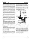
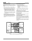
3 Volt Suspend
The Core Logic module supports the stopping of the CPU
and system clocks for a 3V Suspend state. If appropriately
configured, via the Clock Stop Control register (F0 Index
BCh), the Core Logic module asserts internal SUSP_3V
after it has gone through the SUSP#/SUSPA# handshake.
SUSP_3V is a state indicator, indicating that the system is
in a low-activity state and Suspend Modulation is active.
This indicator can be used to put the system into a low-
power state (the system clock can be turned off).
Internal SUSP_3V is connected to the enable control of the
clock generators, so that the clocks to the CPU and the
Core Logic module (and most other system devices) are
stopped. The Core Logic module continues to decrement
all of its device timers and respond to external SMI inter-
rupts after the input clock has been stopped, as long as the
32 KHz clock continues to oscillate. Any SMI event or
unmasked interrupt causes the Core Logic module to de-
assert SUSP_3V, restarting the system clocks. As the CPU
or other device might include a PLL, the Core Logic module
holds SUSP# active for a pre-programmed period of delay
(the PLL re-sync delay) that varies from 0 to 15 ms. After
this period has expired, the Core Logic module de-asserts
SUSP#, stopping Suspend. SMI# is held active for the
entire period, so that the CPU reenters SMM when the
clocks are restarted.
Save-to-Disk
Save-to-Disk is supported by the Core Logic module. In
this state, the power is typically removed from the Core
Logic module and from the entire SC2200, causing the
state of the legacy peripheral devices to be lost. Shadow
registers are provided for devices which allow their state to
be saved prior to removing power. This is necessary
because the legacy AT peripheral devices used several
write only registers. To restore the exact state of these
devices on resume, the write only register values are
“shadowed” so that the values can be saved by the power
management software.
The PC/AT compatible keyboard controller (KBC) and
floppy port (FDC) do not exist in the SC2200. However, it is
possible that one is attached on the ISA bus or the LPC
bus (e.g., in a SuperI/O device). Some of the KBC and FDC
registers are shadowed because they cannot be safely
read. Additional shadow registers for other functions are
described in Table 6-29 "F0: PCI Header/Bridge Configura-
tion Registers for GPIO and LPC Support" on page 198.
F
eff
= F
GX1
x
Asserted Count
Asserted Count + De-asserted Count