60 AMD Geode™ SC2200 Processor Data Book
Signal Definitions
32580B
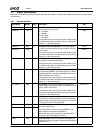
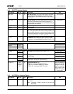
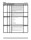
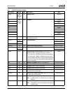
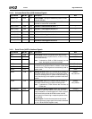
PERR# H2 I/O Parity Error. PERR# is used for reporting data parity
errors during all PCI transactions except a Special Cycle.
The PERR# line is driven two PCI clocks after the data in
which the error was detected. This is one PCI clock after
the PAR that is attached to the data. The minimum dura-
tion of PERR# is one PCI clock for each data phase in
which a data parity error is detected. PERR# must be
driven high for one PCI clock before being placed in TRI-
STATE. A target asserts PERR# on write cycles if it has
claimed the cycle with DEVSEL#. The master asserts
PERR# on read cycles.
This signal is internally connected to a pull-up resistor.
---
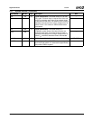
SERR# H1 I/O System Error. SERR# can be asserted by any agent for
reporting errors other than PCI parity. When the PFS bit
is enabled in the GX1 module’s PCI Control Function 2
register (Index 41h[5]), SERR# is asserted upon asser-
tion of PERR#.
This signal is internally connected to a pull-up resistor.
---
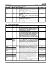
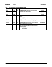
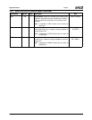
REQ1# A5 I Request Lines. REQ[1:0]# indicate to the arbiter that an
agent requires the bus. Each master has its own REQ#
line. REQ# priorities (in order) are:
1) VIP
2) IDE Channel 0
3) IDE Channel 1
4) Audio
5) USB
6) External REQ0#
7) External REQ1#
Each REQ# is internally connected to a pull-up resistor.
---
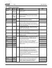
REQ0# B5 ---
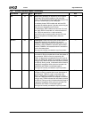
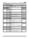
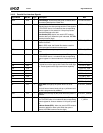
GNT1# C6 O Grant Lines. GNT[1:0]# indicate to the requesting mas-
ter that it has been granted access to the bus. Each mas-
ter has its own GNT# line. GNT# can be retracted at any
time a higher REQ# is received or if the master does not
begin a cycle within a minimum period of time (16 PCI
clocks).
Each of these signals is internally connected to a pull-up
resistor.
GNT0# must have a pull-up resistor of 1.5 KΩ and
GNT1# must have a pull-down resistor of 1.5 KΩ.
DID1 (Strap)
GNT0# C5 DID0 (Strap)
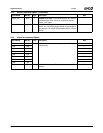
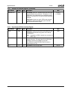
3.4.6 PCI Bus Interface Signals (Continued)
Signal Name BalL No. Type Description Mux


