


AMD Geode™ SC2200 Processor Data Book 227
Core Logic Module - Bridge, GPIO, and LPC Registers - Function 0
32580B
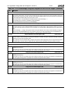
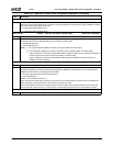
Index F4h Second Level PME/SMI Status Register 1 (RC) Reset Value: 00h
The bits in this register contain second level status reporting. Top level status is reported in F1BAR0+I/O Offset 00h/02h[0].
Reading this register clears the status at both the second and top levels.
A read-only “Mirror” version of this register exists at F0 Index 84h. If the value of the register must be read without clearing the SMI
source (and consequently de-asserting SMI), F0 Index 84h can be read instead.
7:3 Reserved. Reads as 0.
2 GPWIO2 SMI Status. Indicates whether or not an SMI was caused by a transition on the GPWIO2 pin.
0: No.
1: Yes.
To enable SMI generation:
1) Ensure that GPWIO2 is enabled as an input: F1BAR1+I/O Offset 15h[2] = 0.
2) Set F1BAR1+I/O Offset 15h[6] = 1 to allow SMI generation.
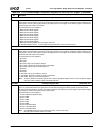
1 GPWIO1 SMI Status. Indicates whether or not an SMI was caused by a transition on the GPWIO1 pin.
0: No.
1: Yes.
To enable SMI generation:
1) Ensure that GPWIO1 is enabled as an input: F1BAR1+I/O Offset 15h[1] = 0.
2) Set F1BAR1+I/O Offset 15h[5] to 1 to allow SMI generation.
0 GPWIO0 SMI Status. Indicates whether or not an SMI was caused by a transition on the GPWIO0 pin.
0: No.
1: Yes.
To enable SMI generation:
1) Ensure that GPWIO0 is enabled as an input: F1BAR1+I/O Offset 15h[0] = 0.
2) Set F1BAR1+I/O Offset 15h[4] to 1 to allow SMI generation.
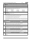
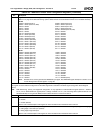
Index F5h Second Level PME/SMI Status Register 2 (RC) Reset Value: 00h
The bits in this register contain second level status reporting. Top level status is reported in F1BAR0+I/O Offset 00h/02h[0].
Reading this register clears the status at both the second and top levels.
A read-only “Mirror” version of this register exists at F0 Index 85h. If the value of the register must be read without clearing the SMI
source (and consequently de-asserting SMI), F0 Index 85h can be read instead.
7 Video Idle Timer SMI Status. Indicates whether or not an SMI was caused by expiration of Video Idle Timer Count Regis-
ter, (F0 Index A6h).
0: No.
1: Yes.
To enable SMI generation, set F0 Index 81h[7] = 1.
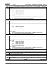
6 User Defined Device Idle Timer 3 (UDEF3) SMI Status. Indicates whether or not an SMI was caused by expiration of User
Defined Device 3 (UDEF3) Idle Timer Count Register (F0 Index A4h).
0: No.
1: Yes.
To enable SMI generation, set F0 Index 81h[6] = 1.
5 User Defined Device Idle Timer 2 (UDEF2) SMI Status. Indicates whether or not an SMI was caused by expiration of User
Defined Device 2 (UDEF2) Idle Timer Count Register (F0 Index A2h).
0: No.
1: Yes.
To enable SMI generation, set F0 Index 81h[5] = 1.
4 User Defined Device Idle Timer 1 (UDEF1) SMI Status. Indicates whether or not an SMI was caused by expiration of User
Defined Device 1 (UDEF1) Idle Timer Count Register (F0 Index A0h).
0: No.
1: Yes.
To enable SMI generation, set F0 Index 81h[4] = 1.
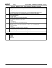
Table 6-29. F0: PCI Header/Bridge Configuration Registers for GPIO and LPC Support (Continued)
Bit Description